


Fiat Uno Manual
Steering angles and front wheel alignmentSteering / Steering angles and front wheel alignment
1 Accurate front wheel alignment is essential to provide good steering and roadholding characteristics and to ensure slow and even tyre wear. Before considering the steering angles, check that the tyres are correctly inflated, that the front wheels are not buckled, the hub bearings are not worn or incorrectly adjusted and that the steering linkage is in good order, without slackness or wear at the joints.
2 Wheel alignment consists of four factors: Camber, is the angle at which the road wheels are set from the vertical when viewed from the front or rear of the vehicle. Positive camber is the angle (in degrees) that the wheels are tilted outwards at the top from the vertical.
Castor, is the angle between the steering axis and a vertical line when viewed from each side of the vehicle. Positive castor is indicated when the steering axis is inclined towards the rear of the vehicle at its upper end.
Steering axis inclination, is the angle when viewed from the front or rear of the vehicle between vertical and an imaginary line drawn between the upper and lower suspension strut mountings.
Toe, is the amount by which the distance between the front inside edges of the roadwheel rims differs from that between the rear inside edges.
3 If the distance between the front edges is less than that at the rear, the wheels are said to toe-in. If the distance between the front inside edges is greater than that at the rear, the wheels toe-out.
4 Camber and castor are set during production of the car and are not adjustable.
Any deviation from specification will be due to collision damage or to gross wear in the components concerned.
5 To check the front wheel alignment, first make sure that the lengths of both tie-rods are equal when the steering is in the straight-ahead position. Measure between the locknut at the balljoint and the ball cup at the end of the rack housing by passing a thin rod under the rack of the gaiter. If adjustment is required, release the locknut and turn the tie-rod.
6 Obtain a tracking gauge. These are available in various forms from accessory stores or one can be fabricated from a length of steel tubing suitably cranked to clear the sump and bellhousing and having a setscrew and locknut at one end.
7 With the gauge, measure the distance between the two wheel inner rims (at hub height) at the rear of the wheel. Push the vehicle forward to rotate the wheel through 180º (half a turn) and measure the distance between the wheel inner rims, again at hub height, at the front of the wheel. This last measurement should differ from (be less than) the first by the appropriate toe-in according to the Specification (see Specifications Section).
8 Where the toe-in is found to be incorrect, release the tie-rod balljoint locknuts and turn the tie-rods equally. Only turn them a quarter of a turn at a time before re-checking the alignment. Viewed from the centre line of the car, turning the tie-rod clockwise will decrease the toe-in.
9 Make sure that the gaiter outboard clip is released otherwise the gaiter will twist as the tie-rod is rotated.
10 Always turn both rods in the same direction when viewed from the centre line of the vehicle otherwise the rods will become unequal in length. This would cause the steering wheel spoke position to alter and cause problems on turns with tyre scrubbing.
11 On completion, tighten the tie-rod balljoint locknuts without altering their setting. Check that the balljoint is at the centre of its arc of travel and then retighten the gaiter clip.
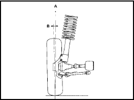
Fig. 10.6 Camber angle (Sec 8)
A Vertical line
B Camber angle (positive)
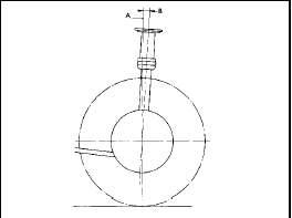
Fig. 10.7 Castor angle (Sec 8)
A Vertical line
B Castor angle (positive)
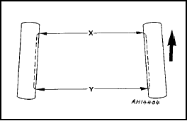
Fig. 10.8 Front wheel alignment diagram (Sec 8)
X Front dimension
Y Rear dimension
Y - X = Toe-in


