


Fiat Uno Manual
Electrical systemSupplement: Revisions and information on later models / Electrical system
Alternator (999 and
1108 cc models) -
removal and refitting
1 To remove the alternator from 999 cc
engine models, disconnect the leads from the
terminals on its rear face.
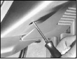
2 Extract the screws and remove the plastic drivebelt guard.
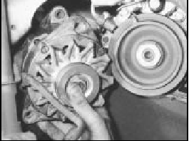
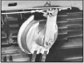
3 Slacken the mounting and adjuster bolts, push the alternator in towards the engine and remove the drivebelt.
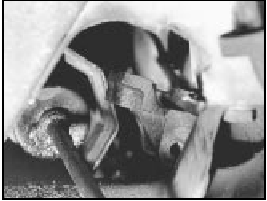
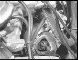
4 Remove the mounting and adjuster bolts, and withdraw the alternator downwards through the gap between the right-hand driveshaft and the engine sump pan (photo).
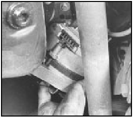
15.4 Removing the alternator from the 999 cc engine
5 Refitting is a reversal of removal; re-tension the drivebelt.
Alternator (later models) -
removal and refitting
6 Disconnect the battery negative lead.
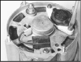
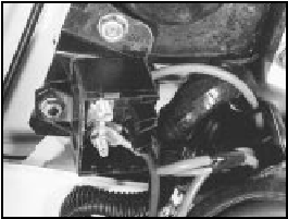
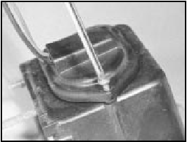
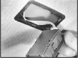
7 Loosen off the right-hand front roadwheel bolts, then raise and support the car at the front end on axle stands. Remove the right-hand roadwheel.
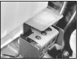
8 Remove the wheel arch underwing shield by driving the compression pins from the centre of the retaining clips (using a 2 mm drift), then prise free the panel retaining clips and remove the shield. Keep the pins and clips in a safe place and renew any that may have been damaged during removal (photo).
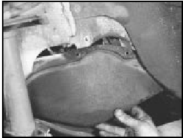
15.8 Remove the wheel arch lower guard panel for access to the alternator
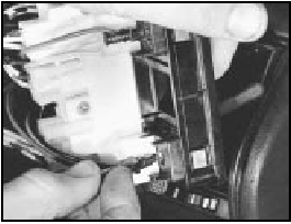
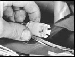
9 Detach the wiring connector from the alternator.
10 Release the alternator mounting and belt adjuster link bolts, and take off the drivebelt.
11 Take out the alternator top and bottom mounting bolts.
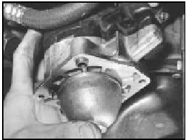
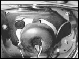
12 Disconnect the air cooling hose from the rear cover of the alternator, and then unscrew the fixing nuts and take off the rear cover with hose spout. Mark the position of the cover on the alternator before removing it, so that the spout will be correctly positioned when refitted (photos).
15.12A Alternator air cooling hose
15.12B Alternator rear cover and fixing nut
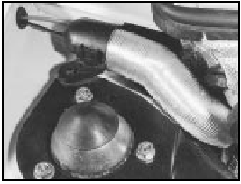
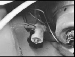
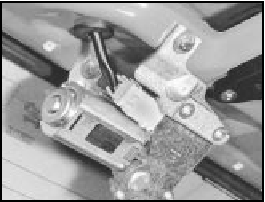
13 Unbolt the driveshaft bearing support/alternator bracket from the engine crankcase, and swivel the support downwards to provide space for withdrawal of the alternator (photo).
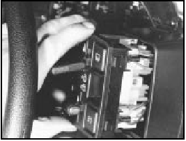
15.13 Driveshaft bracket swivelled downwards
14 Withdraw the alternator from under the right-hand front wing (photo).
15.14 Withdrawing the alternator
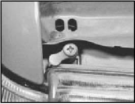
15 Refit in the reverse order of removal. Refit the drivebelt and ensure correct engagement with the pulleys, then set the drivebelt tension and tighten the alternator retaining nuts.
Alternator brushes -
renewal
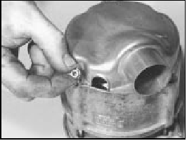
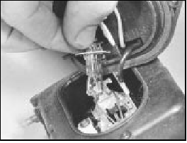
16 Depending on model, the brush holder is
secured by two screws, which should be extracted
and the brush holder removed (photos).
15.16A Extracting the alternator brush holder screw
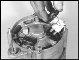
15.16B Removing the alternator brush holder
17 New brushes and the holder are supplied as an assembly.
Starter motor
(999 cc models) -
removal and refitting
18 To remove the starter motor from 999 and
1108 cc models, first disconnect the leads
from the starter motor terminals.
19 Release the washer fluid reservoir flexible bag from the engine compartment rear bulkhead and move it to the left-hand side.
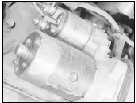
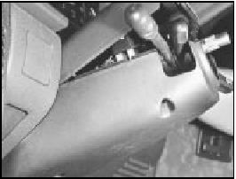
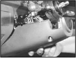
20 Unscrew the starter motor mounting bolts, withdraw the starter from the flywheel bellhousing, and then lift it out of the left-hand side of the engine compartment (photo).
15.20 Starter motor removal from the 999 cc engine
21 Refitting is a reversal of removal.
Starter motor (1301 cc Turbo ie,
1372 cc ie,
1372 cc Turbo ie) -
removal and refitting
22 Disconnect the battery. Working from
under the front end of the car, unscrew the
starter motor mounting bolts and disconnect
the electrical leads.
23 Withdraw the starter motor downwards. On Turbo models, there is just enough clearance, if the oil cooler hose and the oil pressure switch lead are deflected carefully aside (photos).
15.23A Starter motor removal from the 1301 cc Turbo ie engine
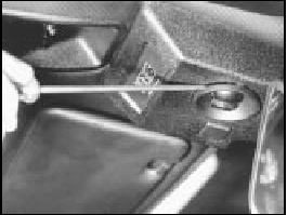
15.23B Starter motor and wiring connections on the 1372 cc ie engine
24 Refit by reversing the removal operations.
Starter motor brushes
(later models) - renewal
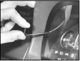
25 When renewing the starter motor brushes
on later models, the old brushes will need to
be crushed (in a vice or with a hammer) and
their leads then soldered to the new brushes.
Fuses - later models
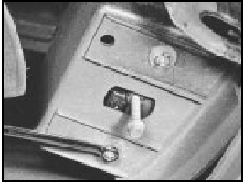
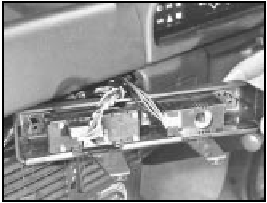
26 The fuse arrangement is slightly different
on later models, but the circuits protected are
still identified by a symbol. Refer to the
Specifications Section for full details. Note
also the terminal block with plastic cover,
which can be used to isolate the battery from
the electrical system by disconnecting the
leads from the terminals (photos).
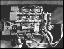
15.26A Fuse block on the 1301 cc Turbo ie model
15.26B Battery lead terminal block on the 1301 cc Turbo ie model
Relays (Turbo ie models) -
general
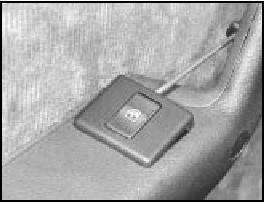
27 On Turbo ie models, the relays mounted
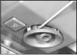
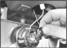
in the fuse block are as shown in Fig. 13.103.
Additional relays are located as follows:
Headlamp relay - on lead under main fuse
block
Fuel injection system main control relay -
adjacent to airflow meter
Headlamps later models
28 The headlamp units fitted on later models
differ according to model, but the bulb and
unit replacement details are generally the
same as described for previous models in
Chapter 9. Note that the rubber cover can
only be fitted with the tab to the top as shown
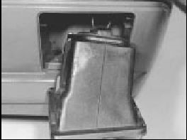
(photo).
15.28 Headlamp unit fitted to the 1372 cc ie model
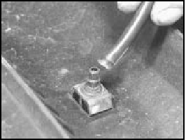
Headlamp beam adjusters for
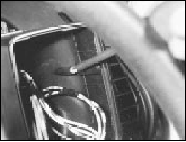
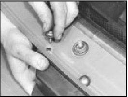
load compensation - later
models
29 Some later models are fitted with
headlamp beam adjusters which allow
temporary resetting to be made (such as
when the car is fully loaded). Access to these
adjusters is made by lifting the bonnet (photo).
15.29 Headlamp beam adjuster on the 999 cc Turbo ie model
30 Turn the adjusters anti-clockwise to lower the beam to the normal level or clockwise to raise the beam (when the car is unloaded).
Repeat the procedure on the opposite headlamp unit an equal amount.
31 Other later models have separate horizontal and vertical beam adjusters, positioned as shown (photos). A load compensating lever is attached to the adjusters to enable temporary resetting of the headlamp beams, without changing the normal adjustment. Turn the lever to the appropriate side (right or left) to make the adjustment as required. The normal setting adjustment procedures are the same as those outlined for the previous model units in Chapter 9, but ensure that the load compensation lever is turned to the “O” (normal load setting) position before making any adjustments.
15.31A Headlamp horizontal beam alignment adjuster screw on a 1372 cc ie
model
15.31B Headlamp vertical beam alignment adjuster screw on a 1372 cc ie model.
Note the load compensator lever which is set in the “O” (normal load) setting
position
Headlamp unit removal - later
models
32 The removal and refitting procedures
described in Chapter 9 also apply to the later
headlamp type, but note that later units are
secured in position by three retaining screws.
Headlamp dim-dip system -
description
33 On later models, the wiring circuit has
been modified to prevent the car being driven
on parking lamps only in built-up areas.
34 Headlamp intensity is reduced by the transformer located at the front of the engine compartment (photo).
15.34 Headlamp dim-dip transformer
35 Any attempt to start the car with parking lamps only on will automatically cause the headlamps to switch on with a low-intensity dipped beam. Dipped and main beam function normally.
36 The headlamp dim-dip system is a legal requirement for all UK models registered after April 1st, 1987.
Front fog lamps - bulb/unit
removal and refitting
and beam adjustment
37 Ensure that the front fog lamps are
switched off, then unscrew the two retaining
screws and withdraw the lamp unit from the
underside of the front bumper (photos).
15.37A Undo the retaining bolts . . .
15.37B . . . and withdraw the front fog lamp unit . . .
38 Undo the retaining screw and remove the access cover from the unit (photo).
15.38 . . . remove the rear cover . . .
39 Disconnect the wiring connector from the bulb, release the clips and withdraw the bulb from the lamp (photo).
15.39 . . . detach the wires, extract the bulb
40 Refit in the reverse order of removal.
Check the light for satisfactory operation and if the beam requires resetting, turn the adjustment screw in the required direction.
41 To adjust the beam, position the car 5 m from, and square on to, a wall or similar.
42 Measure the height of the centre of the lamp lens from the ground and mark the position on the wall. Switch on the lamp. The demarcation line (cut-off) of the light should be below the mark on the wall by 50 mm plus one-third of the ground-to-lamp centre measurement. Adjust the beam as required using the long centre screw.
Horn - relocation
43 The single horn, on applicable models, is
now located behind the grille, bolted on a
bracket attached to the top rail (photo).
15.43 Horn location
Steering column combination
switches (later models) -
removal and refitting
44 Disconnect the battery negative lead.
45 Undo the retaining screws and remove the steering column shrouds (photos).
15.45A Undo the retaining screws . . .
15.45B . . . then remove the upper . . .
15.45C . . . and the lower column shroud . . .
46 Remove the steering wheel as described in Chapter 10.
47 Loosen off the switch-to-column clamp screw, disconnect the wiring connectors to the switch and withdraw the switch from the column (photos).
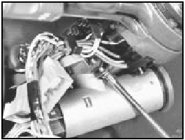
15.47A Undo the retaining screw . . .
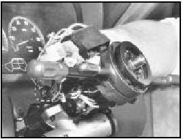
15.47B . . . and remove the column switch
48 Refit in the reverse order of removal, but ensure that the lug of the switch aligns with the slot in the column as it is fitted into position. Check for satisfactory operation of the switches on completion.
Instrument panel
(Turbo ie models) -
removal and refitting
49 The instrument panel on these models
incorporates an engine oil pressure gauge
and a turbo boost gauge. The latter is
connected directly to the inlet manifold.
50 Apart from disconnecting the boost gauge rubber hose, the instrument panel removal and refitting procedure is as described in Chapter 9 for the 1301 cc model or from paragraph 57 in this Section for the 1372 cc model.
51 A digital electronic instrument panel is available as an option on Turbo ie models.
The removal and refitting procedures differ from analogue instrument panels in respect of the electrical connections - a speedometer drive cable is not used.
Facia-mounted switches
(1301 cc Turbo ie model) -
removal and refitting
52 Disconnect the battery.
53 Insert a thin-bladed screwdriver into the joint between the switch block and the switch block housing, to depress the plastic retaining tabs. Do this carefully, otherwise the switch block or casing will be damaged.
54 Withdraw the switch block. Individual switches can now be pushed out of the block.
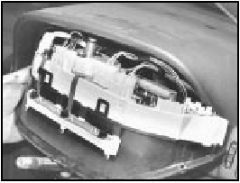
Fibre optics are used to illuminate some switches, these simply pull out of their sockets (photos). The illumination bulb is located on a crossmember found behind the instrument pack. Removal of instruments/top cover allows access.
15.54A Switch block withdrawal on the 1301 cc Turbo ie model
15.54B Disconnecting a fibre optic cable from its holder on the 1301 cc Turbo
ie model
55 The switch housing can be removed after extracting the fixing screws (photos).
15.55A Facia switch housing lower screw removal on the 1301 cc Turbo ie model
15.55B Facia switch housing inner screw removal on the 1031 cc Turbo ie model
56 Refitting is a reversal of removal.
Instrument panel
(later models) -
removal and refitting
57 Disconnect the battery negative lead.
58 Unscrew and remove the two instrument panel-to-facia retaining screws (photo).
15.58 Remove the retaining screws . . .
59 Remove the lower facia trim panel, which is secured by two screws and a nut. Reach up to the rear of the instrument panel to disconnect the speedometer cable, then push the panel from its recess in the facia.
Disconnect the multi-connectors from the rear face of the panel and withdraw it (photo).
15.59A . . . withdraw the instrument panel . . .
15.59B . . . and disconnect the speedometer cable
60 Refit in the reverse order of removal.
Ensure that the speedometer cable is fully engaged as the unit is refitted into position.
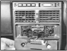
Auxiliary control panel
(later models) -
removal and refitting
61 Disconnect the battery negative lead.
62 Insert the flat of a screwdriver under the trim piece at the end of the auxiliary panel as shown and prise it free. Repeat the procedure and remove the trim piece at the other end of the panel (photo).
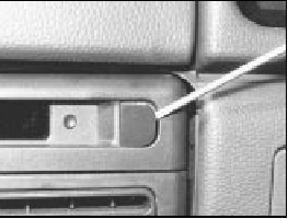
15.62 Prise free the trim covers for access to retaining screws . . .
63 Undo the retaining screws, withdraw the panel from the facia. Disconnect the wiring connectors from the panel switches to remove the panel completely (photo).
15.63 . . . and withdraw the auxiliary control panel
64 A switch bulb can be renewed by untwisting the holder and removing the holder and bulb.
65 A switch unit can be removed from the panel by unscrewing the four retaining screws.
66 Refitting is a reversal of the removal procedure. Ensure that the wiring connections are securely made and check for satisfactory operation of the switches on completion.
Heater control panel
(later models) -
removal and refitting
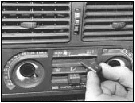
67 Disconnect the battery negative lead.
68 Pull free the heater/fresh air and blower control knobs (photo).
15.68 Remove the control knobs . . .
69 Undo the two retaining screws and withdraw the control panel from the facia (photos). Detach the wiring connectors from the panel illumination lights and remove the panel.
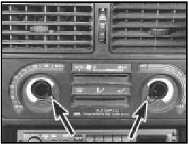
15.69A . . . undo the retaining screws (arrowed)
15.69B . . . and withdraw the heater control panel
70 Refitting is a reversal of the removal procedure. Ensure that the wiring connections are securely made and on completion check that the operation of the controls is satisfactory.
Trip master
71 This electronic instrument is fitted into the
check panel of 1100SL and 1300SL models
from 1986.
72 The device provides information on fuel consumption, range, speed and elapsed time.
73 With the ignition key turned to MAR, figures are displayed in respect of the last journey - average fuel consumption, average speed and elapsed time (up to switching off the ignition).
74 As soon as the engine is started, the instrument processes the current values to include fuel consumption, range and the actual time.
75 Fuel consumption is only displayed when the road speed exceeds 8.0 km/h (5.0 mph).
76 The fuel range is only displayed after a road speed of between 25.0 and 70.0 km/h (15.0 to 44.0 mph) has been maintained for at least 90 seconds or at higher speeds for 22 seconds.
77 A reset button is provided, also a display change button (from instant to average or total values). Should the instrument reading exceed 99 hours, 59 minutes or 1000 km (622 miles) depressing the display change button will display all zeros. Depress button E to resume normal function.
78 Refer to the end of the manual for a wiring diagram of the check panel, incorporating the trip master.
Interior roof mounted spotlamp,
switch and/or clock -
removal and refitting
79 Disconnect the battery negative lead.
80 Prise free the lamp unit from its aperture in the roof panel using a thin-bladed screwdriver. The lamp bulb can be inspected by untwisting the holder and withdrawing it from the rear of the unit (photos). Extract the bulb from the holder if it requires renewal.
15.80A Prising free the roof-mounted spotlamp
15.80B Roof-mounted spotlamp bulb removal
81 To remove the lamp switch from the panel, reach through the lamp aperture and press it free from the roof panel (photo).
Detach the wiring connectors.
15.81 Roof-mounted spotlamp switch removal
82 To remove the clock, reach through the lamp aperture and undo the retaining screws (photo). Withdraw the clock and detach the wiring connectors.
15.82 Roof-mounted clock retaining screw removal
83 Refitting is a reversal of the removal procedure. Reset the clock on completion.
Central door locking system 84 Certain later models, equipped with a central door locking system, have an infra-red remote control for opening the door locks.
85 It is important that the battery used in the hand control is renewed when necessary with one of identical type (Duracell 7H34). This is only available as a FIAT spare part (No 7595393).
86 The remote control door lock receiver unit can be removed by carefully prising it free from the roof panel and disconnecting the wiring connector (photo).
15.86 Remote control receiver unit removal
87 If either this unit or the hand control are renewed at any time, recoding will be necessary and this is a task best entrusted to a FIAT dealer.
Cigar lighter
(later models) -
removal and refitting
88 Pivot back the cover and lift out the ashtray.
89 Undo the retaining screws and remove the trim together with the lighter unit. Detach the wiring connector and release the lighter unit from the panel.
90 Refit in the reverse order of removal.
Electrically operated windozw
switches -
removal and refitting
91 The window regulator switches on later
models are located in the door pull trim. To
remove a switch, prise it free from the trim by
inserting a thin-bladed screwdriver under the
switch flange, then lever it free from its
aperture (photo). Take care not to damage the
trim. Detach the wiring connector to fully
remove the switch.
15.91 Prising free the window regulator switch from the armrest
92 Refit in the reverse order of removal and then check the operation of the switch.
Windscreen wiper motor
(later models) -
removal and refitting
93 Disconnect the battery negative lead.
94 Remove the bonnet as described in Chapter 12.
95 Remove the wiper arm and blade as described in Chapter 9, then unscrew and remove the pivot nut (photo).
15.95 Unscrewing the wiper pivot nut
96 Undo the air inlet grille retaining screws noting that two are not fitted with washers.
Where applicable, remove the washer reservoir filler cap from the reservoir neck protruding through the grille. Carefully prise free and lift the air inlet grille clear of the body.
As it is lifted, invert it and detach the washer hose from the washer nozzle (photos).
15.96A Release the air grille from its fixing points . . .
15.96B . . . and detach the windscreen washer hose
97 Where applicable, detach and remove the washer reservoir from the recess in the front of the windscreen to allow access to the wiper motor.
98 Unscrew and remove the two wiper motor retaining screws. Lower and withdraw the unit, then detach the cover from the motor.
Disconnect the wiring from the wiper motor and withdraw it from the car (photos).
15.98A Remove the wiper motor retaining screws . . .
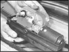
15.98B . . . separate the wiper motor from its cover . . .
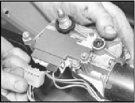
15.98C . . . and detach the wiring connector
99 Refit in the reverse order of removal.
Check for satisfactory operation of the wiper and washer on completion.
Windscreen washer reservoir
(Turbo ie models) -
removal and refitting
100 Disconnect the battery negative lead.
101 Remove the bonnet as described in Chapter 12.
102 Remove the wiper arm and blade as described in Chapter 9, then unscrew and remove the pivot nut.
103 Undo the air inlet grille retaining screws noting that two are not fitted with washers.
Where applicable, remove the washer reservoir filler cap from the reservoir neck protruding through the grille. Carefully prise free and lift the air inlet grille clear of the body.
As it is lifted, invert it and detach the washer hose from the washer nozzle.
104 Syphon any remaining washer fluid from the reservoir, then disconnect it and partially withdraw it from the recess in front of the windscreen so that the wiring connection and the washer supply hoses (to the windscreen washer and the rear screen washer nozzles) can be detached from the pump unit. Remove the reservoir from the vehicle.
105 Refit in the reverse order of removal. If the washer pump unit was detached from the reservoir, use a new seal washer when refitting it. Top up the reservoir and check the screen washers for satisfactory operation before refitting the grille panel and the wiper arm/blade.
Tailgate wiper motor
(later models) -
removal and refitting
106 Although the tailgate wiper motor differs
in appearance, its removal and refitting
procedures are much the same as those
described for the earlier models in Section 27
of Chapter 9 (photo).
15.106 Tailgate wiper motor - later model
Radio
107 All later models are now equipped with
power supply and speaker leads for radio
installation.
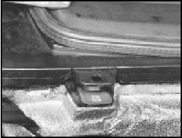
108 Installation of the standard FIAT aerial mounted on the windscreen pillar is shown (photos).
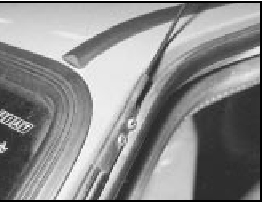
15.108A Pillar upper screws for aerial
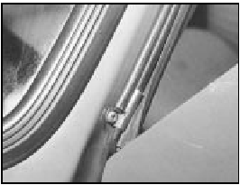
15.108B Pillar lower screw for aerial
Check control system sensors -
description
109 The locations of the sensors referred to in
Chapter 9, Section 34 are given in the
following paragraphs, and their construction
differs according to their individual function.
Brake fluid level sensor 110 This is mounted in the master cylinder fluid reservoir cap, and comprises a pair of reed switches in a glass bulb, and a magnet at the end of a float.
111 When the fluid level is correct, the magnetic flux closes the switches. In the event of a leak in the system, the magnet moves away, the switches open and the warning lamp comes on.
Brake disc pad wear sensor 112 This is basically a circuit wire embedded in the pad friction material. As the pad wears, the wire is eventually exposed and contacts the disc, whereupon the warning lamp comes on to indicate that pad renewal is necessary.
Coolant level sensor
113 This is located in the cooling system
expansion tank, and is of the reed switch
type, which operates in a similar way to that
described for the brake fluid sensor.
Engine oil level sensor
114 This is located at the end of the dipstick,
and comprises a pair of switches at the end of a
bi-metallic strip, heated by electrical resistance.
115 The heat is dissipated by the immersion of the dipstick in the engine oil, so preventing the bi-metallic strip from curving so much that the switches would open.
116 If the oil level drops, the heat is no longer dissipated, the switches open, and the warning lamp comes on.
Door closure sensor
117 The sensor consists of a microswitch
within the lock. The switch actuates the
warning lamp according to whether the lock is
in the open or closed mode.
Check control system sensors -
testing
Brake fluid level sensor
118 With the fluid level correct, switch on the
ignition and depress the centre of the
reservoir cap. If the sensor switches are
working correctly, then “FAULT” should be
indicated on the check panel.
Coolant level sensor
119 With the coolant level in the expansion
tank correct, switch on the ignition and then
pull the wiring plug from the sensor. “FAULT”
should be indicated on the check panel. If it is
not, then it is the panel which is faulty.
120 An ohmmeter should be used to check for continuity, holding the float in both the full and low level positions.
Engine oil level sensor
121 With the oil level correct, disconnect the
wiring plug from the dipstick, and then bridge
the plug terminals (not dipstick side) with a 12
ohm resistor. Switch on the ignition.
122 If the red light on the check panel goes out, then the fault is due to the sensor.
123 If the light stays on, then it is the check panel module which is faulty.
Door closure sensor
124 Any fault in the lock microswitch can best
be detected using an ohmmeter.
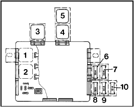
Fig. 13.103 Auxiliary fuses and relays on 1301 cc Turbo ie models (Sec 15)
1 Horn relay
2 Heated rear screen relay
3 Foglamps relay
4 Radiator fan relay
5 Electric windows relay
6 Foglamps fuse
7 Radiator fan second speed fuse
8 Fuel injector fan fuse
9 Electric windows fuse
10 Electric fuel pump fuse


