


Fiat Uno Manual
Clutch
Clutch pedal - adjustment
(cable clutch)
1 The method of adjusting the clutch has
been revised.
2 Fully depress the clutch pedal two or three times.
3 Using a suitable measuring stick placed in contact with the floor panel (carpet peeled back), measure dimension “X” in Fig. 13.87.
This dimension must be taken between the centre of the pedal pad and the floor, first with the pedal in the fully depressed position, and then in the fully released position.
4 The dimension measured should fall within the range quoted in the Specifications for this Supplement.
5 Any adjustment which may be required should be carried out by slackening the locknut on the cable at the release lever (on top of the gearbox) and turning the adjusting nut. Tighten the locknut on completion.
Hydraulic clutch - description 6 Some later models are fitted with an hydraulically operated clutch in place of the cable operated type. The main components of the system are a master cylinder, with separate hydraulic fluid reservoir, and the operating cylinder. The master cylinder is mounted in-line with and just forward of the clutch pedal. The operating cylinder is mounted within a housing on top of the transmission. The fluid reservoir is located in the engine compartment and is mounted on the left-hand side near the bulkhead. No settings or specific procedures are given by the manufacturer at the time of writing.
Maintenance
(hydraulic clutch)
7 Periodically check the fluid level in the
reservoir. If the level has dropped, top it up
with the specified fluid. The fluid level must
not be allowed to drop below the MIN level
mark on the side of the reservoir (photos). If
the fluid level drops by a significant amount, it
is indicative of a leak in the hydraulic circuit
and this must therefore be traced and
repaired at the earliest opportunity.
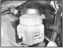
11.7A Clutch hydraulic fluid reservoir showing MIN and MAX markings
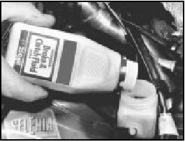
11.7B Topping up the fluid level in the clutch fluid reservoir
8 Inspect the fluid lines and connections for security and any signs of leaks.
Clutch master cylinder -
removal, overhaul
and refitting
9 If the cylinder is to be dismantled, it will first
be necessary to obtain a cylinder repair kit.
Start by detaching and removing the trim panel from the underside of the facia on the driver’s side.
10 Place a suitable covering over the floor carpet to prevent staining in the event of fluid spillage. Clamp the fluid supply hose at the master cylinder end, then unscrew the retaining clip and detach the hose from the cylinder. Position the hose out of the way and with its end pointing up.
11 Detach the operating rod clevis from the brake pedal.
12 Unscrew and detach the hydraulic pipe to the operating cylinder from the master cylinder (photo).
11.12 Clutch master cylinder and hydraulic pipe connections
13 Undo the two retaining nuts and withdraw the master cylinder.
14 To dismantle the cylinder, prise free and pull back the dust boot, extract the retainer and withdraw the operating rod.
15 Invert the cylinder and shake free the piston and seal assembly. If it is stuck inside the cylinder, apply moderate air pressure (from a foot pump) into the tail end and catch the assembly in a clean cloth as it is ejected.
16 Remove the seals noting their orientation.
Clean all components in methylated spirits or new hydraulic fluid. If the cylinder is damaged, scored or badly worn it must be renewed. The seals must always be renewed once they are removed.
17 Assemble the new seals to the piston and lubricate the cylinder, seals and piston assembly with new hydraulic fluid (of the specified type) before assembling them.
Ensure that the seals are fitted the correct way round (as noted during removal).
18 Renew the dust boot, fit and secure the operating rod into position with the retainer, then refit the dust boot over the cylinder.
19 If the intake pipe connector was removed, this must be refitted using a new seal.
20 Refit the cylinder in the reverse order of removal. Connect and hand tighten the hydraulic pipe to the operating cylinder before fully tightening the cylinder securing nuts. The hydraulic pipe can then be fully tightened.
21 Reconnect the fluid supply hose to the cylinder and tighten the retaining clip to secure. Release the clamp.
22 Top up the clutch fluid level in the reservoir then bleed the system as described later in this Section.
Clutch operating cylinder -
removal, overhaul
and refitting
23 If the cylinder is to be dismantled once it
is removed, it will first be necessary to obtain
a cylinder repair kit. Access is much improved
by first detaching the appropriate ducts and
hoses from the areas directly above the
cylinder, on top of the transmission/clutch
housing.
24 To avoid excessive fluid loss when the hydraulic line is detached from the operating cylinder, remove the filler cap from the reservoir, place a clean piece of polythene sheet over the filler neck and refit the reservoir cap.
25 Unscrew the union nut and detach the hydraulic fluid line from the operating cylinder (photo).
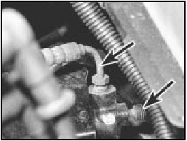
11.25 Clutch operating cylinder showing hydraulic line connection and bleed
nipple (arrowed)
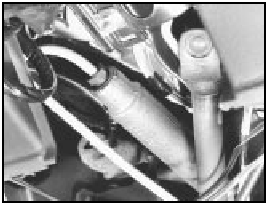
26 Undo the cylinder/mounting bracket retaining bolts and lift clear the cylinder together with the bracket (photo). Release the retaining clip and separate the cylinder from the bracket.
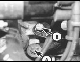
11.26 Clutch operating lever (A) and operating cylinder
bracket-to-transmission housing bolt (B)
27 To dismantle the cylinder, prise free and pull back the dust boot, withdrawing it together with the operating rod.
28 Invert the cylinder and shake free the piston and seal assembly. If it is stuck inside the cylinder, remove the bleed screw then apply moderate air pressure (from a foot pump) into the bleed port and catch the cylinder in a clean cloth as it is ejected.
29 Remove the seals noting their orientation.
Clean all components in methylated spirits or new hydraulic fluid. If the cylinder is damaged, scored or badly worn it must be renewed. The seals must always be renewed once they are removed.
30 Assemble the new seals to the piston and lubricate the cylinder, seals and piston assembly with new hydraulic fluid (of the specified type) before assembling them.
Ensure that the seals are fitted the correct way round (as noted during removal).
31 Renew the dust boot, fit and secure the operating rod into position then refit the dust boot over the cylinder. If removed, refit the bleed screw.
32 Reconnect the cylinder to the mounting bracket and refit the combined assembly to the vehicle in the reverse order of removal.
Ensure the hydraulic union is clean and take care not to damage the threads as it is reconnected.
33 Remove the polythene seal from the hydraulic reservoir filler neck, top up the fluid level and bleed the system as described below.
Clutch hydraulic system -
bleeding
34 The clutch hydraulic circuit is bled in
much the same manner to that described for a
brake circuit. Refer to Section 12 in Chapter 8
and proceed as described, but note that the
bleed screw for the clutch circuit is located in
the end of the operating cylinder (see
photo 11.25). The clutch hydraulic circuit
reservoir is mounted in the engine
compartment on the left-hand side near the
bulkhead and is separate from the master
cylinder. As the system is being bled, ensure
that the fluid level in the reservoir is
maintained between the MIN and MAX level
marks. Do not allow the fluid level to drop
below the MIN level mark otherwise air will
enter the system and greatly lengthen the
operation. Wipe clean any fluid spillage from
the paintwork or adjacent components as it
has a corrosive effect if left.
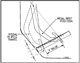
Fig. 13.87 Clutch pedal adjustment diagram - cable clutch (Sec 11)
For dimension “X” , refer to Specifications
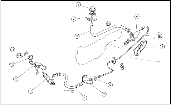
Fig. 13.88 Exploded view of the hydraulic clutch components (Sec 11)
1 Filler cap
2 Fluid reservoir
3 Hose
4 Master cylinder
5 Cover
6 Clip
7 Bracket
8 Hose
9 Operating cylinder
10 Bracket
11 Circlip
12 Operating lever


