
Fiat Uno Manual
Fuel and exhaust systemsSupplement: Revisions and information on later models / Fuel and exhaust systems
Warning: Many of the
procedures in this Section
require the removal of fuel lines
and connections that may result
in some fuel spillage. Before carrying out
any operation on the fuel system refer to
the precautions given in ‘Safety first!’ at
the beginning of this Manual and follow
them implicitly. Petrol is a highly
dangerous and volatile liquid, and the
precautions necessary when handling it
cannot be overstressed.
Caution: On fuel injection
models, the system is
pressurised, therefore extra
care must be taken when
disconnecting fuel lines. When
disconnecting a fuel line union, loosen the
union slowly, to avoid a sudden release of
pressure that may cause fuel to spray out
and have a container and cloth ready to
catch spillages. Fuel pressure checking
must be entrusted to a Fiat dealer, or other
specialist, who has the necessary special
equipment.
PART A: GENERAL
Unleaded fuel
Note: On models with catalytic converters
only unleaded petrol must be used - the use
of leaded petrol will destroy the catalyst.
1 It is possible to use unleaded fuel (minimum 95 RON) in the following models with the indicated serial numbers.
Engine Serial number
903 cc 146A.000
146A.046
146A.048
999 cc 156A2.00
1108 cc 160A3.000
1116 cc 138B.000
138B.046
146A4000
146A4.048
1299/1301 cc 138B2.000
138B2.046
149A7.000
1149A7.000
146A2.000
1372 cc 146C1.000
146A8.000
160A1.046
2 On all except the 903 cc engine, the use of
unleaded fuel is conditional upon the
avoidance of constant high speeds and
sudden acceleration.
Air cleaner - modified types 3 The air cleaner on later models is of the automatic temperature controlled type. The need to move the intake control lever to winter or summer positions is no longer required.
4 The air cleaner on the 999 cc engine is of rectangular shape and the element is removed for renewal after prising back the toggle type clips (photos).
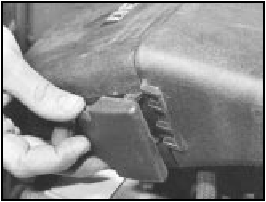
9A.4A Air cleaner toggle clip on the 999 cc model
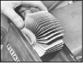
9A.4B Air cleaner element on the 999 cc model
5 To remove this type of air cleaner, disconnect the cold and hot air intake hoses and the large and small breather hoses (photos).
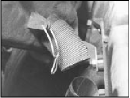
9A.5A Air cleaner hot air intake and lower retaining clip on the 999 cc model
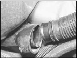
9A.5B Air cleaner cold air intake on the 999 cc model
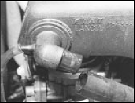
9A.5C Air cleaner breather hoses on the 999 cc model
6 Unscrew the nut from the upper casing section and then release the lower toggle type clip and lift the air cleaner from the carburettor (photo). Note the sealing ring between the air cleaner and the carburettor. Unless the ring is in good condition, renew it.
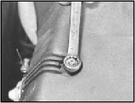
9A.6 Air cleaner casing nut on the 999 cc model
7 If the thermostatically-controlled cold air flap opener in the air cleaner casing is faulty (checked by holding a mirror against the cold air intake when the engine is warm), renew the opener (single fixing screw); no repair is possible (photo).
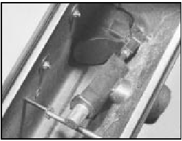
9A.7 Air cleaner thermostatic flap opener on the 999 cc model
8 The air cleaner on the 1116 cc and 1299/1301 cc engine is of circular type.
Access to the element is obtained by extracting the three cover nuts and lifting off the lid (photos).
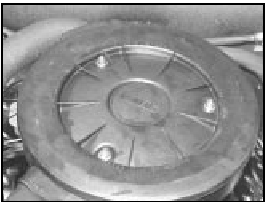
9A.8A Air cleaner on the 1116 cc, 1299 cc and 1301 cc models
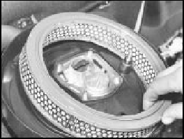
9A.8B Circular type air cleaner element
9 The air cleaner casing can be removed after unscrewing the four nuts which hold it to the carburettor and the single nut on the camshaft cover bracket. As the casing is withdrawn, disconnect the hoses from it (photos).
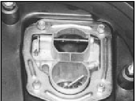
9A.9A Circular type air cleaner fixing nuts
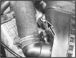
9A.9B Circular type air cleaner nut on the camshaft cover (arrowed)
10 The thermostatically-controlled cold air flap opener is similar to that described in paragraph 7.
11 The air cleaner on the 1372 cc ie engine is of rectangular shape. The element can be removed after releasing the spring clips at the front of the unit, followed by the two screws from its top face. The air cleaner end cover can then be withdrawn and the element removed. The air cleaner unit on the 1372 cc Turbo ie engine is located in the front right-hand corner of the engine compartment.
Prise free the four clips to release the top cover and expose the element.
Fuel pump (999 and 1108 cc
carburettor models) -
description, removal
and refitting
12 The fuel pump is mechanically-operated
via a pushrod which is in contact with an
eccentric cam on the camshaft. The pump is
of sealed, disposable type - no repair or
cleaning being possible.
13 To remove the pump, disconnect the flexible hoses and unbolt the pump from the cylinder head. Retain the pushrod and the insulator block.
14 Refitting is a reversal of removal, use new gaskets, one on each side of the insulator block.
Fuel tank (999 and 1108 cc
engines)
15 In conjunction with the plastic type fuel
tank, the breather and fuel level transmitter
unit have been modified as shown in
Fig. 13.35.
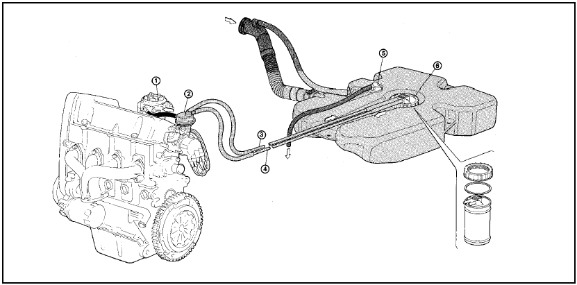
Fig. 13.35 Fuel tank and supply circuit on the 999 and 1108 cc engines (Sec
9A)
1 Carburettor
2 Fuel pump
3 Fuel return pipe
4 Fuel feed pipe
5 Tank vent valve
6 Fuel level sender unit
PART B:
CARBURETTOR MODELS
Carburettor (Weber 32 TLF) -
description
Warning: Refer to the beginning
of this Section before starting
any work.
1 This carburettor is used on the 999 cc engine and is of the single venturi downdraught type, with a manually-operated choke (cold start).
2 The unit incorporates an automatic anti-flooding device, a full power valve and an accelerator pump (photos).
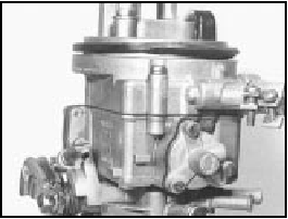
9B.2A Weber 32 TLF 4/250 carburettor from anti-run-on solenoid valve side
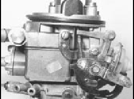
9B.2B Weber 32 TLF 4/250 carburettor from choke linkage side
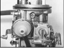
9B.2C Weber 32 TLF 4/250 carburettor from accelerator pump side
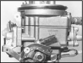
9B.2D Weber 32 TLF 4/250 carburettor from throttle linkage side
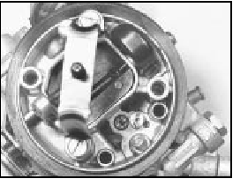
9B.2E Weber 32 TLF 4/250 carburettor from above
3 The throttle valve block, although incorporating coolant hose stubs, is not in fact coolant-heated.
4 A solenoid-operated idle cut-off valve is fitted to prevent running-on (dieseling) when the ignition is switched off.
Carburettor (Weber 32 TLF) -
idle speed and mixture
adjustment
5 If the car is not equipped with a rev counter,
connect one in accordance with the
manufacturer’s instructions.
6 Have the engine at normal operating temperature and idling. Turn the idle speed screw on the carburettor until the speed matches that specified (photo).
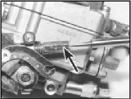
9B.6 Weber 32 TLF 4/250 carburettor idle speed screw (arrowed)
7 The idle mixture is set in production, and the adjustment screw is sealed with a tamperproof cap. If, however, the idling is not smooth or the engine or carburettor have been extensively overhauled, the mixture may require adjusting.
8 Prise out the tamperproof plug and connect an exhaust gas analyser to the car in accordance with the instrument manufacturer’s instructions (photo).
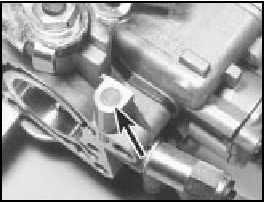
9B.8 Weber 32 TLF 4/250 carburettor mixture screw location under tamperproof
plug (arrowed)
9 With the engine at normal operating temperature and idling at the specified speed, turn the mixture screw until the CO percentage is within the specified tolerance (photo).
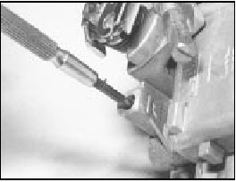
9B.9 Mixture adjustment - Weber 32 TLF carburettor
10 If an exhaust gas analyser is not available, turn the mixture screw anti-clockwise to obtain maximum idle speed and then turn it clockwise until the speed just starts to drop.
Re-adjust the idle speed screw to bring the idle speed to the specified level.
11 Switch off the engine and remove the test instruments. It is advisable to fit a new tamperproof cap to the mixture screw if it is intended to take the vehicle overseas. This is required to meet legislation in certain countries.
Carburettor (Weber 32 TLF)
- removal and refitting
12 Remove the air cleaner.
13 Release the clips and disconnect the fuel hoses from the carburettor. Take extreme care that fuel spillage is contained and that there are no naked flames in the vicinity of the work area. Do not smoke.
14 Disconnect the distributor vacuum hose from the carburettor.
15 Release the clamp screw and pinch-bolt, and disconnect the choke cable.
16 Slacken the throttle cable by releasing the locknut and turning the adjuster sleeve, then slip the cable nipple out of the notch in the throttle spindle quadrant.
17 Disconnect the lead from the idle cut-off solenoid valve.
18 Unscrew the two long mounting bolts and lift the carburettor from the inlet manifold (photo).
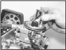
9B.18 Removing the Weber 32 TLF carburettor by gripping air cleaner mounting
bracket
19 Refitting is a reversal of removal, but observe the following points (photo).
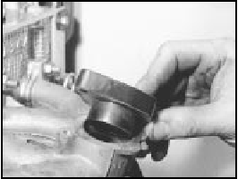
9B.19 Carburettor insulator block
a) Use a new flange gasket at each side of the insulator block.
b) Check that the choke cable is fitted so that full choke can be obtained but the choke is fully off when the choke control lever is pushed right in.
c) Adjust the throttle cable so that there is just a slight amount of slackness when the accelerator pedal is released, but when fully depressed, full throttle can be obtained (throttle valve plate quadrant up against its stop).
Carburettor (Weber 32
TLF) - overhaul
20 It is rare for a carburettor to require
complete overhaul and if the unit has seen
considerable service and wear is detected in
the throttle valve spindle bushes, it is
recommended that a new or rebuilt carburettor
is obtained.
21 Normally, the following operations are all that will be required to keep the carburettor working perfectly. The unit need not be removed from the manifold unless the throttle block is to be detached; simply remove the air cleaner.
22 Periodically, unscrew the large hexagonal plug adjacent to the fuel inlet pipe, extract the filter and clean it. Refit the filter and plug (photo).
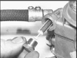
9B.22 Fuel filter removal from the Weber 32 TLF carburettor
23 Obtain a repair kit for your carburettor which will contain all the necessary replacement gaskets and seals. Extract the top cover and choke diaphragm assembly fixing screws, remove the small plastic cover and push out the bush, then lift the top cover from the carburettor. Discard the gasket (photos).
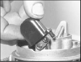
9B.23A Choke linkage cover removal from the Weber 32 TLF carburettor
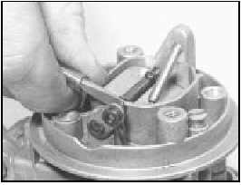
9B.23B Disconnecting the choke linkage on the Weber 32 TLF carburettor
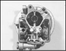
9B.23C Underside view of the cover on the Weber 32 TLF carburettor
24 Mop out fuel and sediment from the float chamber.
25 The various jets and calibrated bleeds can then be removed and cleared by blowing them through with air from a tyre pump. Do not attempt to clear them by probing with wire, as this will ruin the calibration.
26 Check the tightness of the fuel inlet needle valve. If necessary, remove the float and its pivot pin so that a close-fitting ring spanner can be used on the valve body. Take care to support the pivot pin pedestals as the pin is tapped out - they are brittle. The throttle valve plate block can be removed after extracting the screws (photos).
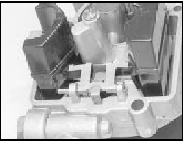
9B.26A Floats and pivot pin arrangement on the Weber 32 TLF carburettor

9B.26B Fuel inlet valve needle removal from the Weber 32 TLF carburettor
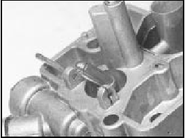
9B.26C Fuel inlet valve body and washer removal from the Weber 32 TLF
carburettor
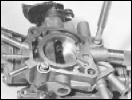
9B.26D Extracting the throttle valve block screws from the Weber 32 TLF
carburettor
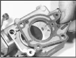
9B.26E Throttle valve block gasket on the Weber 32 TLF carburettor
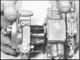
9B.26F Main parts of the Weber 32 TLF carburettor
27 As reassembly progresses, carry out the following checks and adjustments.
Float level - checking and adjustment 28 With the carburettor top cover held vertically so that the float arm just touches the fuel inlet needle valve ball, measure between the float and the surface of the flange gasket as shown in Fig. 13.36. If the dimension is not within the specified tolerance, bend the float tab which bears on the needle valve ball.
Fast idle - adjustment (requires removal of the carburettor) 29 Close the choke valve plate by moving the control lever fully. Retain the lever in this position with a rubber band.
30 The throttle valve plate should now be open to give a gap between its edge and the progression holes as specified. Check the gap using a twist drill of equivalent diameter.
31 If adjustment is required, release the locknut and turn the adjustment screw.
Retighten the locknut.
Automatic anti-flooding device -
adjustment
32 Operate the choke valve plate lever fully.
33 Move the control lever on the automatic anti-flooding device downwards to simulate vacuum pull-down. The choke butterfly should open, leaving a gap (B - Fig 13.38) as specified. Measure the gap with a twist drill of equivalent diameter and make sure that the choke valve plate is in the position shown. If adjustment is required, turn the screw on the diaphragm unit.
Carburettor
(Weber 30/32 DMTE) - general
34 The carburettor is of twin barrel
downdraught type with a manually-operated
choke and an electronic fuel cut-off overrun
valve (photos).
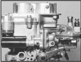
9B.34A Weber 30/32 DMTE carburettor from anti-flood device link side
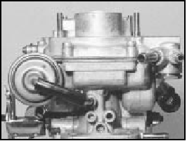
9B.34B Weber 30/32 DMTE carburettor from diaphragm hose side
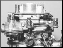
9B.34C Weber 30/32 DMTE carburettor from choke link side
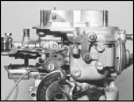
9B.34D Weber 30/32 DMTE carburettor from throttle link side
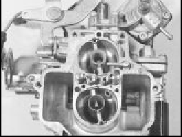
9B.34E Weber 30/32 DMTE carburettor from above (with cover removed)
35 Periodically, remove the large hexagonal plug from its location at the fuel inlet pipe stubs, and clean any dirt from the filter gauge.
Idle speed and mixture adjustment 36 Refer to Chapter 3, Section 7 (photos).
Removal and refitting
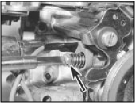
9B.36A Showing idle speed screw (arrowed) and . . .

9B.36B . . . mixture screw (arrowed) on the Weber 30/32 DMTE carburettor
37 The operations are similar to those described for the Weber 32 TLF earlier in this Supplement, but note that the carburettor is secured by four nuts and additional electrical leads must be disconnected (photos).
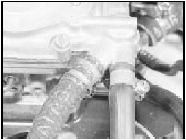
9B.37A Fuel inlet and return hoses on the Weber 30/32 DMTE carburettor
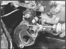
9B.37B Throttle cable connection on the Weber 30/32 DMTE carburettor
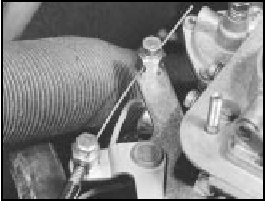
9B.37C Choke cable connection on the Weber 30/32 DMTE carburettor

9B.37D Electrical lead to automatic antiflood device on the Weber 30/32 DMTE
carburettor

9B.37E Carburettor lead connectors on the Weber 30/32 DMTE carburettor
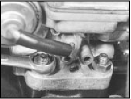
9B.37F Unscrewing a carburettor fixing nut
Carburettor (Weber 30/32
DMTE) - overhaul
38 The carburettor top cover with float may
be removed without the need to withdraw the
carburettor from the manifold. Other
adjustments described in this sub-Section,
however, will require removal of the
carburettor.
39 Disconnect the short, curved diaphragm hose from the top cover.
40 Extract the top cover screws, lift the cover from the carburettor body, and rotate it in order to release the cranked choke control rod from its key hole (photo). Mop out the fuel and clean the jets.
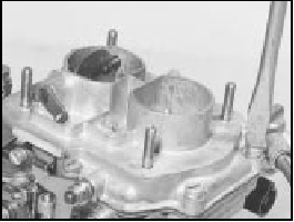
9B.40 Unscrewing a top cover screw from the Weber 30/32 DMTE carburettor
41 Check the jet sizes and other components against those listed in the Specifications, in case a previous owner has substituted incorrect components (photo).
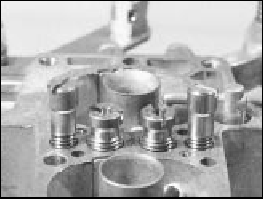
9B.41 Jets on the Weber 30/32 DMTE carburettor (top cover removed)
42 Overhaul procedures are generally as given in Chapter 3, Section 14 for the Weber 30/32 DMTR, but use the Specifications listed in this Chapter. Additional overhaul procedures are given here.
Fuel inlet needle valve
43 If a high float level causing flooding of the
carburettor has been evident, first check that
the inlet valve housing is tight, and its washer
is sealing satisfactorily. A leak here will cause
fuel to bypass the inlet valve.
44 If the needle valve is to be renewed, remove it in the following way.
45 Access to the fuel inlet needle valve is obtained by carefully tapping out the float arm pivot pin. Take care, the pivot pin pillars are very brittle (photo).
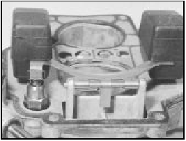
9B.45 Float pivot arrangement and needle valve on the Weber 30/32 DMTE
carburettor
46 Unscrew the fuel inlet valve body and remove the valve and washer.
47 When refitting the new valve, always use a new sealing washer.
Float stroke (travel) - see Fig. 3.10 48 The float stroke should be between 42.5 and 43.5 mm when measured from the top cover gasket. Adjust if necessary by bending the tab on the end of the arm.
Accelerator pump
49 Adjustment of the accelerator pump is
very rarely required, but if performance is
suspect, carry out the following operations.
50 Fill the carburettor float chamber and then operate the throttle valve plate lever several times to prime the pump.
51 Position a test tube under the accelerator pump jet and give ten full strokes of the throttle lever, pausing between each stroke to allow fuel to finish dripping.
52 The total volume of fuel collected should be as specified. Adjust the nut on the pump control if necessary to increase or decrease the volume of fuel ejected.
General
53 When the stage is reached where the
valve plate spindle bushes have worn, then
the carburettor should be renewed complete.
54 When reassembling the carburettor, use new gaskets which can be obtained in a repair pack.
Carburettor (Weber 32 ICEV
61/250 and DMTE 30/32,
DMTE 30/150) - general
55 These carburettor types are fitted to later
models according to engine type. They are
similar in structure and operation to their
equivalents described in Chapter 3. Reference
can therefore be made to that Chapter for the
description and any operations concerning
them, but refer to Section 2 of this Chapter for
their specifications.
Carburettor (Solex
C 30/32-CIC 8) - description
56 This carburettor is fitted as an alternative
to the Weber unit on 1116 cc models
produced for certain markets. The removal,
refitting and overhaul procedures are
essentially the same as described earlier for
the Weber carburettors.

Fig. 13.36 Float level measurement - Weber 32 TLF carburettor (Sec 9B)
A = 26.75 to 27.25 mm (1.05 to 1.07 in)

Fig. 13.37 Fast idle adjustment - Weber 32 TLF carburettor (Sec 9B)
A = 0.65 to 0.75 mm (0.026 to 0.030 in)

Fig. 13.38 Automatic anti-flooding device adjustment - Weber 32 TLF
carburettor (Sec 9B)
B = 4.5 mm (0.18 in)
PART C:
BOSCH LE2-JETRONIC
FUEL INJECTION SYSTEM
Description
Warning: Refer to the beginning
of this Section before starting
any work.
1 The Bosch LE2-Jetronic fuel injection system, fitted to the 1301 cc Turbo ie model, is an electronically controlled multi-point injection (MPi) system.
2 The fuel injectors are fed at constant pressure in relation to inlet manifold vacuum pressure.
3 The system electronic control unit (ECU) actuates the injectors for variable duration, and so supplies the precise volume of fuel required for any given engine speed and load condition.
4 The ECU also monitors the air induction, air temperature, coolant temperature and throttle opening as additional parameters to compute the required opening of the fuel injectors, giving maximum power with fuel economy.
Fuel supply system
5 The fuel supply system consists of an
electric pump and primary filter, located
adjacent to the fuel tank. A fuel pressure peak
damper is located next to the pump (photo).
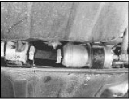
9C.5 Electric fuel pump/filter/pressure damper assembly location on a 1301 cc
Turbo ie model
6 Fuel is then pumped through a filter to the fuel rail and injectors. The injectors are of the solenoid-operated type, actuated from the ECU.
7 Fuel pressure is regulated according to inlet manifold vacuum pressure by a fuel pressure regulator. Excess unpressurised fuel is returned to the fuel tank.
Airflow meter
8 This component measures the quantity of
air drawn into the engine, and converts this
into an electric signal which is transmitted to
the ECU.
9 The intake air exerts a force on the floating plate (1) (Fig. 13.39) which is connected to a potentiometer (2).
10 A compensating butterfly valve (3) compensates for any reflex pressure which may occur, and is subject to the braking effect of the damper chamber (4).
11 The idle mixture (air/fuel ratio) is altered by means of the screw (8), which alters the cross-section of the bypass channel (7).
12 An integral-type temperature sensor is fitted, the resistance value of which decreases as the temperature of the intake air increases.
This facility is used to correct the mixture strength within a pre-determined air temperature range.
Throttle valve housing
13 The housing incorporates a conventional
butterfly-type throttle valve, actuated by
cables and rods from the accelerator pedal.
14 The idle bypass channel (2) (Fig. 13.40) is fitted with an adjustment screw (3) to vary the idle speed.
15 The other screw (4) and locknut are used to set the closing position of the throttle valve plate.
Supplementary air valve
16 This controls the air volume requirement
during cold starting. Essentially, the valve is an
electrically-heated bi-metallic strip, which rotates
the plate (4) (Fig. 13.41) to vary the volume of air
being drawn in through the aperture (1),
according to the temperature of the engine.
17 The requirement for additional air during cold starting is to dilute the additional fuel, which is injected and controlled by the ECU as a result of monitoring the engine coolant temperature sensor.
Electrical control circuit 18 The main components of the system are the ECU and the system control relay. The relay incorporates a fuel cut-off facility, which cuts off the fuel supply in the event of engine failure, the vehicle turning over, or a fuel line breaking. The relay energises the following electrical components.
19 Coolant temperature sensor, which signals the coolant temperature to the ECU.
20 Throttle position switch, which signals the ECU when the throttle valve plate is closed, in order to actuate the deceleration fuel cut-off device at speeds above 2500 rpm.
21 The switch also signals the ECU at full throttle, so that the mixture can be enriched to cope with full-power requirements.
22 The system control relay also monitors the engine speed directly from the ignition coil primary winding.
Maintenance
23 Regularly check the security of all system
hoses, wiring connections and plugs.
24 At the intervals specified in Section 3, renew the fuel filter and the air cleaner element.
Fuel filter - renewal
25 This is located within the engine
compartment just above the timing belt cover.
Disconnect the fuel hoses, but be prepared for loss of fuel (photo).
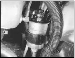
9C.25 Secondary fuel filter
26 When fitting the new filter, make sure that the arrow stamped on it is pointing towards the fuel injector rail.
Air cleaner element -
renewal
27 Prise back the toggle-type clips and take
off the air cleaner lid. Remove and discard the
element, and wipe any dirt from the inside of
the casing (photos).
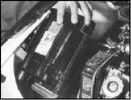
9C.27A Removing the air cleaner lid

9C.27B Removing the air cleaner element
28 Fit the new element and replace the lid.
Idle speed and mixture
adjustment
29 Before carrying out any adjustments, the
engine must be at operating temperature, the
fan having cut in at second speed and then
switched off.
30 Release the locknut and turn the main idle speed screw in the throttle valve housing until the engine idles at the specified speed. This should be all that is necessary to obtain the correct idle speed, as the throttle valve plate base setting is set during production.
However, if wear has taken place, or incorrect adjustment has been carried out previously, proceed in the following way.
31 Disconnect the intake duct from the throttle valve housing. Release the locknut on the base (small) adjusting screw, and turn the screw until there is a clearance between the lower edge of the throttle valve plate and the throat wall of between 0.05 and 0.1 mm (photos).

9C.31A Disconnecting the throttle valve housing intake duct
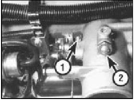
9C.31B Idle speed base setting screw (1) and main adjustment screw (2)
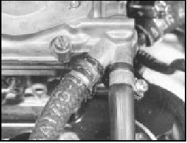
9C.31C Checking throttle valve plate opening with a feeler blade
32 With the engine still at operating temperature, start the engine, and having released the locknut, turn the main (large) idle speed screw fully clockwise to close the bypass passage.
33 Now turn the base (small) screw until the engine idles at between 700 and 800 rpm.
Tighten the locknut.
34 Finally, turn the main (large) adjusting screw to give an idle speed of between 800 and 900 rpm.
35 It is unlikely that the mixture will require alteration, but if it does, connect an exhaust gas analyser to the car in accordance with the equipment manufacturer’s instructions.
36 With the engine at operating temperature, prise out the tamperproof cap, and turn the mixture screw, which is located in the airflow meter, until the CO level is as given in the Specifications. Turning the screw clockwise richens the mixture, turning it anti-clockwise weakens the mixture. Use a close-fitting Allen key for the adjustment (photo).

9C.36 Using an Allen key to adjust the mixture (CO level)
Fuel injection system -
electrical tests
37 When carrying out checks to trace a fault
in the system, an ohmmeter should be used
for the following tests.
38 Disconnect the multipin connector from the ECU, and also the one from the system control relay, and apply the probes of the ohmmeter in accordance with the following sequence to check for continuity in the cables. The component wiring plug will of course be disconnected for the test.
ECU connector Component connector
plug terminal plug terminal
1 1 of ignition coil
2 2 of throttle position
switch
3 3 of throttle position
switch
4 50 of ignition switch
5 Earth
5 5 of airflow meter
7 7 of airflow meter
8 8 of airflow meter
9 9 of airflow meter
9 9 of throttle position
switch
9 18 of supplementary air
valve
9 87 main relay socket
10 10 of coolant temperature
sensor
12 Injector terminals
13 Earth
System control Component connector
relay connector plug terminal
plug terminal
1 1 of ignition coil
15 15 of ignition switch
30 Battery positive
31 Earth
50 50 of ignition switch
87 Injector terminals
87 18 of throttle position
switch
87 9 of ECU multipin socket
87b Fuel pump (fused)
39 Now use the ohmmeter to check the
resistance of the following components.
Supplementary air valve
40 Resistance between the terminals should
be between 40 and 60 ohms at 20ºC (68ºF).
Airflow meter
41 Resistance between terminals 5 and 8 of
the potentiometer should be between 330 and
360 ohms at 20ºC (68ºF).
42 Resistance between terminals 8 and 9 of the internal circuit should be between 190 and 210 ohms at 20ºC (68ºF) and between 170 and 190 ohms at 60ºC (140ºF).
Coolant temperature sensor 43 At 20ºC (68ºF) the resistance should be between 2 and 4 k ohms. At 50ºC (122ºF) the resistance should be between 600 and 900 ohms. At 90ºC (194ºF) the resistance should be between 100 and 300 ohms.
Fuel injectors
44 The winding resistance should be
between 15 and 17 ohms at 20ºC (68ºF).
Throttle position switch 45 With the throttle butterfly valve closed, there should be continuity between terminals 18 and 2, and with the valve fully open, there should be no continuity between terminals 18 and 3.
46 The throttle position switch should not be disturbed unless absolutely necessary. If it has to be removed, then refit it so that the microswitch is heard to click immediately the throttle butterfly is opened.
Fuel injection system -
mechanical tests
Fuel pump
47 To test the pressure of the fuel pump, a
pressure gauge will be required, connected
into the fuel delivery hose.
48 Remove the multipin plug from the system control relay and bridge terminals 87b and 30.
49 Turn the ignition switch on. The pump should operate and indicate a pressure of between 2.8 and 3.0 bars (40 and 44 lbf/in2).
50 To check the operation of the peak pressure regulator, pinch the fuel return hose.
If the fuel pressure increases, the regulator must be faulty, and should be renewed.
51 Check that the fuel pressure increases when, with the engine idling, the accelerator is depressed sharply.
Supplementary air valve
52 With the engine at normal operating
temperature and idling, pinch the
supplementary air valve hose using a pair of
pliers. The engine speed should not drop by
more than 50 rpm. If it does, renew the valve.
Fuel injection system
components -
removal and refitting
53 Disconnect the battery before carrying out
any of the following operations.
Air cleaner
54 Remove the cover and filter element as
previously described.
55 Disconnect the duct from the air cleaner casing, and then unbolt and remove the casing. Note that the lower bracket bolt need not be completely removed, only unscrewed, due to the design of the bracket. The air cleaner metal duct is routed over the top of the radiator (photos).

9C.55A Disconnecting the duct from the air cleaner
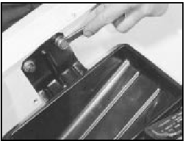
9C.55B Removing the air cleaner casing upper bracket
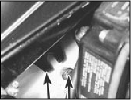
9C.55C Air cleaner casing lower bracket and bolt (arrowed)
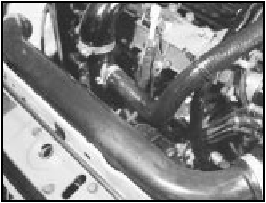
9C.55D Air cleaner metal duct over radiator
Airflow meter
56 Release the securing clip and disconnect
the air intake duct (photo).

9C.56 Air intake duct at airflow meter (securing clip arrowed)
57 Release the securing clip and disconnect the air outlet duct (photo).
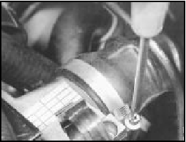
9C.57 Air outlet duct securing clip removal from airflow meter
58 Disconnect the wiring plug.
59 Unscrew the fixing screws and remove the airflow meter from its mounting bracket.
Fuel pressure regulator
60 Disconnect the vacuum hose from the
regulator (photo).
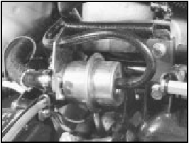
9C.60 Fuel pressure regulator
61 Anticipate some loss of pressurised fuel, and then disconnect the fuel hose from the regulator. Unbolt and remove the unit.
Excessive air pressure switch 62 This is screwed into the end of the inlet manifold. Disconnect the electrical leads and unscrew the switch.
Coolant temperature sensor 63 This is screwed into the cylinder head and has wires connected to it. Drain the cooling system before commencing operations.
64 Disconnect the wiring plug and unscrew the sensor.
Throttle valve housing and inlet
manifold
65 Disconnect the air inlet hose from the
throttle valve housing, and also the
supplementary air valve hose.
66 Disconnect the throttle control cable by swivelling the grooved sector and slipping the cable nipple from its recess.
67 Disconnect the wiring plug from the throttle position (potentiometer) switch.
68 Unbolt the fuel pressure regulator/wiring loom bracket, and also the wiring loom bracket at the other end of the inlet manifold.
Move the wiring loom aside.
69 Unbolt and remove the throttle housing support bracket.
70 Disconnect the vacuum servo hose and the fuel pressure regulator vacuum hoses from the inlet manifold (photos).

9C.70A Brake servo vacuum hose connection to inlet manifold
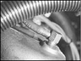
9C.70B Fuel pressure regulator vacuum hose connection at the inlet manifold
71 Disconnect the leads from the excessive air pressure switch.
72 Unscrew the inlet manifold fixing nuts.
Note that double nuts are used at the ends of the manifold in order to secure the exhaust heat shield (photo). The shield should be released and lowered to rest on the exhaust manifold.
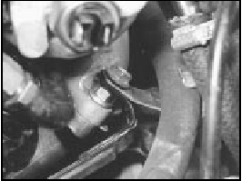
9C.72 Double nuts at the end of the inlet manifold
73 Unscrew and remove the remaining two nuts now exposed by lowering the heat shield and lifting the inlet manifold away (photo).
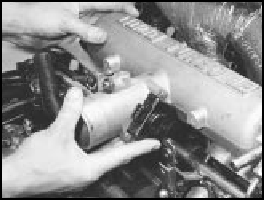
9C.73 Removing the inlet manifold
74 If necessary, the injectors and cooling tube can be withdrawn, and the two twin inlet pipe stubs removed. These are retained with the exhaust manifolds using nuts and washers (photo).

9C.74 Removing an inlet manifold twin pipe stub
Fuel rail and injectors 75 Disconnect the fuel delivery hose from the fuel rail by unscrewing the union nut (photo).
Be prepared for some loss of pressurised fuel.
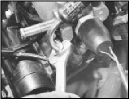
9C.75 Disconnecting the fuel delivery hose union
76 Disconnect the fuel return hose.
77 Unbolt the fuel pressure regulator and the wiring loom brackets (photo).
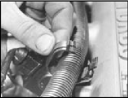
9C.77 Wiring loom clip and bracket
78 Disconnect the air intake hose from the throttle valve housing, and then unbolt and remove the throttle valve housing support bracket (photo).
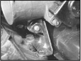
9C.78 Throttle valve housing support bracket
79 Disconnect the hose from the injector cooling fan, and also disconnect the fan thermo-switch on the underside of the injector cooling air duct (photo). Disconnect the injector wiring plugs, and then slide out the injector cooling air duct.
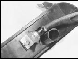
9C.79 Fan thermostatic switch on underside of injector cooling air duct (duct
removed for clarity)
80 The injector retaining plate socket-headed screws may now be removed using an Allen key. Withdraw the fuel injectors and insulators (photos).
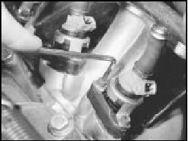
9C.80A Extracting a fuel injector screw
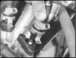
9C.80B Fuel injector removal
81 New injectors, complete with the fuel rail, must be purchased as an assembly. Always use new seals when refitting the injectors and the insulators (photos).
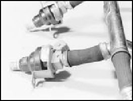
9C.81A Fuel injectors attached to fuel rail
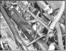
9C.81B Fuel injector cooling air duct refitting
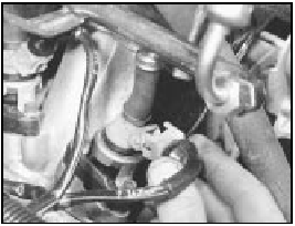
9C.81C Injector wiring plug refitting
Electronic control unit (ECU) 82 The ECU is located under the right-hand side of the facia panel.
83 Pull off the multipin connector plug and extract the fixing screws (photo).
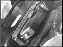
9C.83 ECU multipin plug
System control relay
84 This is located adjacent to the airflow
meter. Pull off the multipin connector and
release the relay fixing (photo).
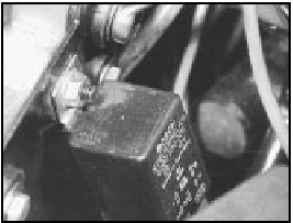
9C.84 Fuel injector system relay
Fuel injector cooling fan 85 This is located low down on the left-hand side of the radiator (photo).
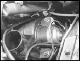
9C.85 Fuel injector cooling fan
86 Remove the spiral-wire-wound hose which connects with the injector cooling duct.
87 Pull off the wiring plug, and unbolt and remove the fan.
Supplementary air valve
88 Disconnect the hoses and wiring plug
from the valve, which is located on the front
face of the engine (photos).
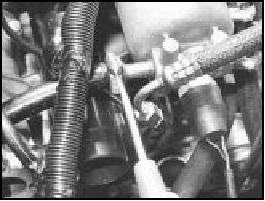
9C.88A Disconnecting the supplementary air valve hose from the inlet manifold
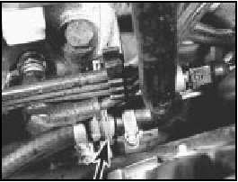
9C.88B Supplementary air valve (arrowed)
89 Unscrew the mounting bracket screws and withdraw the valve.
Throttle position switch
(potentiometer)
90 This is located on the left side of the
throttle valve housing (photo).
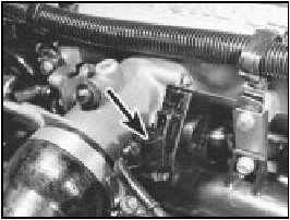
9C.90 Throttle position switch (wiring plug arrowed)
91 Disconnect the wiring plug, unscrew the two fixing screws and withdraw the switch.
Fuel filter
92 Unscrew the fuel line banjo unions from
the filter, which is located in the right-hand
rear corner of the engine compartment. Be
prepared for some loss of pressurised fuel,
and mop it up with rags.
Fuel pump
93 The fuel pump can be removed from its
location beside the fuel tank after
disconnecting the fuel hoses and wiring plug,
and then releasing the mounting clamp.
Refitting all components 94 Refitting of all components is a reversal of removal, but observe the following points.
95 Use new seals and gaskets as applicable, noting that three rubber seals are used on each fuel injector and insulator (photos).
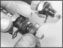
9C.95A Fuel injector large seal
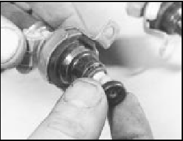
9C.95B Fuel injector small seal
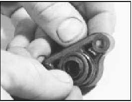
9C.95C Fuel injector insulator seal
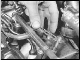
9C.95D Inlet pipe stub gasket
96 Adjust the throttle position switch as described in paragraph 46 of this Section.
97 When refitting a new fuel filter, make sure that the arrow marked on it is in the direction of the fuel flow.
98 Apply gasket cement to the threads of the coolant temperature sensor.
Throttle control linkage -
general
99 This is of the cable and rod type. Adjust the
cable by means of the end fitting and nut, to give
the slightest play in the cable when the plastic
socket is engaged with the ball on the link rod
which runs across the camshaft cover (photos).
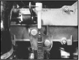
9C.99A Throttle cable and end fitting (primary section)

9C.99B Throttle cable (secondary section) and cross-shaft
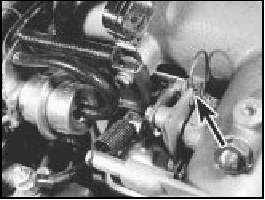
9C.99C Throttle cable nipple (arrowed) in throttle linkage cut-out

9C.99D Throttle cable balljoint retaining spring clip (arrowed)
100 Keep the cross-shaft pivots and return springs lubricated.
Fuel tank - general
101 The fuel tank is of metal construction, but
note the plastic anti-blow-back compartment
between the filler cap and the tank. This is
accessible from under the right-hand wheel
arch (photo).

9C.101 Fuel tank anti-blow-back compartment (arrowed)
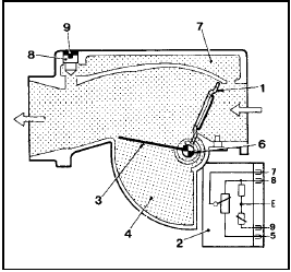
Fig. 13.39 Sectional view of airflow meter - 1301 cc Turbo ie engine (Sec 9C)
1 Floating plate
2 Potentiometer
3 Compensating butterfly valve
4 Damper chamber
6 Spring
7 Bypass channel
8 CO adjusting screw
9 Tamperproof plug
Terminals
5, 7, 8, Potentiometer
9 Air temperature sensor
E Sealed (not to be touched)
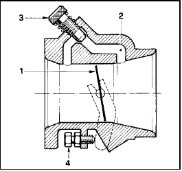
Fig. 13.40 Sectional view of throttle valve housing - 1301 cc Turbo ie engine
(Sec 9C)
1 Butterfly-type throttle valve
2 Idle bypass channel
3 Idle speed adjusting screw
4 Throttle valve plate setting screw
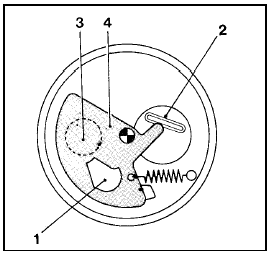
Fig. 13.41 Supplementary air valve - 1301 cc Turbo ie engine (Sec 9C)
1 Aperture
2 Bi-metallic strip
3 Passage
4 Rotating plate (closed position)

Fig. 13.42 ECU and component connector plug terminals - 1301 cc Turbo ie
engine (Sec 9C)
For colour code see main wiring diagrams

Fig. 13.43 System control relay connector plug terminals 1301 cc Turbo ie
engine (Sec 9C)
PART D:
BOSCH MONO-JETRONIC
FUEL INJECTION SYSTEM
Warning: Refer to the beginning
of this Section before starting
any work.
Description
1 The Bosch Mono-Jetronic fuel injection
system fitted to the 1372 cc ie engine and
later 999/1108 ‘FIRE’ models is an electronically-
controlled single point injection (SPi)
system. The SPi system is a compromise
between a conventional carburettor fuel
supply system and a multi-point fuel injection
(MPi) system.
2 Compared with a conventional carburettor, the SPi unit is a relatively simple device. Fuel is pumped to the SPi unit and then injected into the inlet system by a single solenoid valve (fuel injector), mounted centrally on top of the unit. The injector is energised by an electrical signal sent from the electronic control unit (ECU), at which point the injector pintle is lifted from its seat and atomised fuel is delivered into the inlet manifold under pressure. The electrical signals take two forms of current; a high current to open the injector and a low current to hold it open for the duration required. At idle speed the injector is pulsed at every other intake stroke rather than with every stroke as during normal operation.
3 The air-to-fuel mixture ratio is regulated by values obtained from the ignition coil (engine speed), engine coolant temperature sensor, throttle position switch, and the Lambda sensor in the exhaust system. No adjustments to the fuel mixture are possible.
4 The throttle position switch enables the ECU to compute both throttle position and its rate of change. Extra fuel can then be provided for acceleration when the throttle is suddenly opened. Throttle position information, together with the idle tracking switch, provide the ECU with the closed throttle position information.
5 The 1372 cc ie system layout and principal components are shown in Figs. 13.44 and 13.45. Note that the Digiplex 2 electronic ignition, is not fitted to FIRE models (999/1108 cc).
6 The fuel system pump is immersed in the fuel tank and forms a combined unit with the fuel level sender unit. A cartridge type in-line fuel filter is fitted to the fuel line, and is located in the engine compartment.
7 The fuel pressure in the system is controlled by a mechanical diaphragm regulator in the injection unit turret. High pressure in the system causes the diaphragm to operate and excess fuel is returned to the fuel tank.
8 The air intake temperature and volume is regulated to ensure the correct mixture ratio under all operating conditions. The temperature of the air passing through the injection unit is measured by a sensor which transmits such information to the ECU for the necessary processing (photo). A conventional paper type air filter element is used and this must be renewed at the specified intervals.

9D.8 Atmospheric air intake for air temperature sensor (1). Also shown are
the supply and return fuel line connections (2 and 3) and the throttle position
sensor (4)
9 The ECU is specific to the model type, its function being to control the fuel system under all operating conditions, including starting from cold - it richens the fuel mixture as required but at the same time prevents flooding. As the engine temperature rises, the injection impulses are progressively reduced until the normal operation temperature is reached.
10 An integral emergency system enables the fuel injection system to remain operational in the event of any of the following components malfunctioning. These items are the coolant temperature sensor, the air intake sensor, the Lambda sensor, the idle speed check actuator and the throttle position switch. In the event of the throttle position switch malfunctioning, the fuel system becomes automatically inoperative.
11 The catalytic converter fitted in the exhaust system minimises the amount of pollutants which escape into the atmosphere.
The Lambda sensor in the exhaust system provides the fuel injection system ECU with constant feedback which enables it to adjust the mixture to provide the best possible conditions for the converter to operate. The fuel tank ventilation is contained within the system. This is done by feeding any excess vapours through a carbon filter back into the engine intake, using solenoids and valves, as shown in Fig. 13.46.
Maintenance
12 Regularly check the condition and
security of the system hoses and
connections. Also check the system wiring
connections for condition and security.
13 At the specified intervals, renew the air cleaner element and the fuel filter.
Fuel filter - renewal
14 The in-line fuel filter is secured to the
right-hand suspension turret in the engine
compartment. To remove the filter, first
depressurize the fuel in the system as
described later in this Part.
15 Undo the retaining strap bolt and withdraw the filter from its location bracket.
Disconnect the inlet and supply hose from the filter. If crimp connectors are fitted they will have to be cut free and new screw type clips fitted (photo).

9D.15 Secondary fuel filter element
16 Connect the hoses to the new filter ensuring that the filter is correctly orientated (the arrow mark on the body indicates the direction of fuel flow). Ensure that the hose clips are secure before refitting the filter into the retaining strap and securing the retaining bolt. When the engine is restarted, check the hose connections to ensure that there is no fuel leakage from them.
Air cleaner element -
renewal
17 Release the spring clip each side at the
front of the air cleaner, then unscrew and
remove the two screws from the top front face
of the housing. Withdraw the end cover and
element from the filter unit (photos).

9D.17A Release the air cleaner end cover retaining clips . . .

9D.17B . . . remove the cover and extract the element
18 Wipe any dirt from within the casing then locate the new element and refit it together with the end cover.
Idle speed and mixture
adjustment
19 No manual idle speed and/or mixture
adjustments to this type of fuel system are
necessary or possible. Any such adjustments
are automatically made by the ECU. If the
engine idle speed and/or mixture adjustment
is suspect, it must be checked using CO
measuring equipment; a task best entrusted
to a FIAT dealer or a competent garage. The
most probable cause of a malfunction is likely
to be a defective sensor or incorrectly
adjusted accelerator control cable.
Accelerator control system
- check and adjustment
20 To check the adjustment of the
accelerator control system, it is essential that
the engine is at its normal operating
temperature. This is achieved by running the
engine for a period of about fifteen minutes,
by which time the cooling fan should have cut
into operation several times. At this point,
stop the engine, turn the ignition key to the
OFF position and proceed as follows.
21 Remove the air cleaner unit.
22 Place a 10 mm shim (X) between the adjustment screw and the cam lever (between items 1 and 2 in Fig. 13.47), on the throttle body. This will open the thottle butterfly by 20º.

9D.22 Accelerator control rod and cable connections
23 Loosen off the locknuts (C1 and C2) from each linkage end. Insert another 10 mm shim (Y) between the cable support bracket and the nut (C1). Carefully tighten the nut against the shim, ensuring that the cam does not move whilst making the cable slightly taut.
24 Remove the shim (Y) and carefully tighten the nut (C2) against the bracket without allowing the nut (C1) to move. Remove the shim (X) and release the accelerator pedal.
Check that the butterfly is completely open when the the pedal is fully depressed.
Fuel system
depressurisation
Warning: Refer to the beginning
of this Section before starting
any work.
25 The fuel system should always be depressurised whenever any fuel hoses and/or system components are disconnected and/or removed. This can easily be achieved as follows.
26 Loosen off the knurled retaining nut and remove the cover from the fuel pump relay.
This is located on the left-hand suspension turret in the engine compartment (photo).

9D.26 Fuel pump relay (1), injection control relay (2), Lambda sensor fuse
(3) and pump fuse (4) with cover (5) removed
27 Carefully pull free the fuel pump relay, then start the engine and run it until it stops (photo). The fuel system is now depressurised. Turn the ignition off before removing/dismantling any components.

9D.27 Fuel pump relay removal
28 Do not refit the fuel pump relay or turn the ignition on until the system is fully reconnected. When the engine is ready to be restarted, refit the relay and its cover, then restart the engine in the normal manner.
Fuel pump and supply
system checks
29 Specialised equipment is required to
undertake accurate tests in the fuel supply
system and such checks must therefore be
entrusted to a FIAT dealer or a fuel injection
specialist. If the fuel pump is suspected of
malfunction, a basic check can be made by
removing the fuel filler cap then listening
through the filler pipe, get an assistant to turn
on the ignition whilst you listen to hear if the
pump is heard to operate in the tank. If the
pump fails to operate, check that the pump
fuse is sound and that its connection (and
also that of the relay) are clean and secure.
30 The pump can be further checked by first depressurising the fuel system as described in the previous sub-Section, then disconnect the fuel supply pipe at the injector unit and locate it in a suitable container. With the fuel pump relay removed, connect up a suitable test lead with a 7.5 amp (10 amp on models with catalyst) fuse, in series, to the relay terminals 30 and 87, and check that fuel flows into the container from the supply pipe (photo). If a suitable pressure gauge is available for connecting into the fuel line between the engine compartment fuel filter and the injection unit, check that the fuel pressure is as specified at the beginning of this Chapter.

9D.30 T


