


Fiat Uno Manual
Radio/cassette - fittingElectrical system / Radio/cassette - fitting
1 In-car entertainment equipment is not provided as standard on the models covered by this Manual.
2 However, the centre console is designed to receive a radio set after removing the blanking plate behind which a power lead is already provided.
3 The ignition system and other electrical components are suppressed during production of the car and further suppression should not be required other than earthing the wiper motor.
Receiver
4 Fit the radio/cassette using the installation
kit supplied with the equipment.
5 On Comfort models, fit an in-line fuse in the power feed. On Super models the radio supply is protected by fuse number 12.
6 Make sure that the radio is well earthed to a metal body component.
Aerial
7 The recommended locations for the aerial
are towards the rear of the right-hand front
wing or on the windscreen pillar.
8 Fitting instructions for Fiat aerials are supplied with them, but the following general advice will help if using non-Fiat equipment.
9 Motorised automatic aerials rise when the equipment is switched on and retract at switch-off. They require more fitting space and supply leads, and can be a source of trouble.
10 There is no merit in choosing a very long aerial as, for example, the type about three metres in length which hooks or clips on to the rear of the car, since part of this aerial will inevitably be located in an interference field.
For VHF/FM radios the best length of aerial is about one metre. Active aerials have a transistor amplifier mounted at the base and this serves to boost the received signal. The aerial rod is sometimes rather shorter than normal passive types.
11 A large loss of signal can occur in the aerial feeder cable, especially over the Very High Frequency (VHF) bands. The design of feeder cable is invariably in the co-axial form, ie a centre conductor surrounded by a flexible copper braid forming the outer (earth) conductor. Between the inner and outer conductors is an insulator material which can be in solid or stranded form. Apart from insulation, its purpose is to maintain the correct spacing and concentricity. Loss of signal occurs in this insulator, the loss usually being greater in a poor quality cable. The quality of cable used is reflected in the price of the aerial with the attached feeder cable.
12 The capacitance of the feeder should be within the range 65 to 75 picofarads (pF) approximately (95 to 100 pF for Japanese and American equipment), otherwise the adjustment of the car radio aerial trimmer may not be possible. An extension cable is necessary for a long run between aerial and receiver. If this adds capacitance in excess of the above limits, a connector containing a series capacitor will be required, or an extension which is labelled as “capacity-compensated”.
13 Fitting the aerial will normally involve making a 7/8 in (22 mm) diameter hole in the bodywork, but read the instructions that come with the aerial kit. Once the hole position has been selected, use a centre punch to guide the drill. Use sticky masking tape around the area for this helps with marking out and drill location, and gives protection to the paintwork should the drill slip. Three methods of making the hole are in use: a) Use a hole saw in the electric drill. This is, in effect, a circular hacksaw blade wrapped round a former with a centre pilot drill.
b) Use a tank cutter which also has cutting teeth, but is made to shear the metal by tightening with an Allen key.
c) The hard way of drilling out the circle is using a small drill, say 1/8 in (3 mm), so that the holes overlap. The centre metal drops out and the hole is finished with round and half-round files.
14 Whichever method is used, the burr is removed from the body metal and paint removed from the underside. The aerial is fitted tightly ensuring that the earth fixing, usually a serrated washer, ring or clamp, is making a solid connection. This earth connection is important in reducing interference. Cover any bare metal with primer paint and topcoat, and follow by underseal if desired.
15 Aerial feeder cable routing should avoid the engine compartment and areas where stress might occur, eg under the carpet where feet will be located.
Loudspeakers
16 A mono speaker may be located under
the facia panel beneath the glovebox.
17 Provision is made for twin speakers within the door tidy bins or under the rear shelf mountings.
18 Speakers should be matched to the output stage of the equipment, particularly as regards the recommended impedance. Power transistors used for driving speakers are sensitive to the loading placed on them.
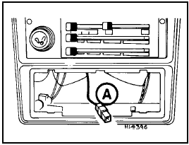
Fig. 9.8 Radio housing and power lead (A) (Sec 30)
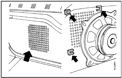
Fig. 9.9 Door speaker mounting (Sec 30)
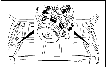
Fig. 9.10 Rear speaker mounting (Sec 30)


