


Fiat Uno Manual
Carburettor Solex C32 DISA 11) - servicing and adjustmentFuel system / Carburettor Solex C32 DISA 11) - servicing and adjustment
1 The carburettor top cover with float may be removed without the need to withdraw the carburettor from the manifold. The other adjustments described will require removal of the carburettor.
2 Extract the top cover fixing screws, disconnect the small externally mounted tension spring and take off the top cover.
3 Access to the fuel inlet needle valve is obtained by carefully tapping out the float arm pivot pin. Take care, the pivot pin pillars are very brittle.
4 Check that the needle valve body is tight otherwise fuel can bypass the needle valve and cause flooding.
Float adjustment
5 Reassemble and check the float setting. Do
this by inverting the top cover so that the
weight of the float fully depresses the ball of
the needle valve. The distance (A) (Fig. 3.16)
between the float and the surface of the top
cover flange gasket should be between 2.0
and 3.0 mm (0.079 and 0.118 in). If
adjustment is required, alter the thickness of
the washer under the needle valve.
Accelerator pump
6 Fill the carburettor float chamber and then
operate the throttle valve plate lever several
times to prime the pump.
7 Position a test tube under the accelerator pump jet and give ten full strokes of the throttle lever, pausing between each stroke to allow fuel to finish dripping.
8 The total volume of fuel collected should be between 2.5 and 4.5 cc. Adjust the nut on the pump control and if necessary to increase or decrease the volume of fuel ejected.
Fast idle adjustment
9 With the choke valve plate fully closed, the
throttle valve plate should be open to give a
dimension (X) (Fig. 3.18) of between 0.90 and
1.0 mm (0.035 to 0.039 in). Use a twist drill of
suitable diameter to measure the gap. If
necessary, adjust by means of the screw and
locknut.
Anti-flooding device
10 Close the choke valve plate by means of
the control lever. At the same time, push the
lean out valve rod towards the valve.
11 There should be a gap (X) (Fig. 3.19) between the edge of the choke valve plate and the carburettor throat of between 4.75 and 5.25 mm (0.187 to 0.207 in). Adjust if necessary by means of the screw and locknut on the lean out valve.
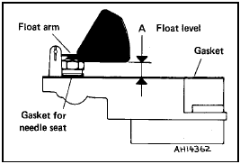
Fig. 3.16 Float setting diagram (Solex C32 DISA 11) (Sec 10)
A = 2.0 to 3.0 mm (0.079 to 0.118 in)
Fig. 3.17 Adjusting accelerator pump rod (Solex C32 DISA 11) (Sec 10)
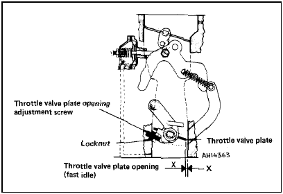
Fig. 3.18 Fast idle adjustment diagram (Solex C32 DISA 11) (Sec 10)
X = 0.90 to 1.0 mm (0.035 to 0.039 in)
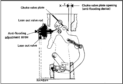
Fig. 3.19 Anti-flooding device adjustment diagram (Solex C32 DISA 11) (Sec
10)
X = 4.75 to 5.25 mm (0.187 to 0.207 in)
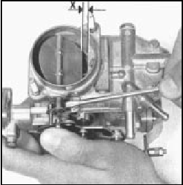
Fig. 3.20 Moving lean out valve rod (Solex C32 DISA 11) (Sec 10)
X = 4.75 to 5.25 mm (0.187 to 0.207 in)


