
Fiat Uno Manual
Braking systemSupplement: Revisions and information on later models / Braking system
PART A: BRAKING
SYSTEM - GENERAL
Front brake pads - all later
models
1 The front brake pads have modified
anti-vibration plates and a wire spring fitted to
prevent them from vibrating and knocking in
operation.
2 On some models the clip securing the disc pad locking block is located on the inboard end, rather than the outer end (shown in Chapter 8). To ensure correct reassembly, check the location of the original block retaining clip before dismantling the brake unit. The alternative fixing arrangement is shown in the accompanying photos, in this instance on a 1372 cc ie model (photos).
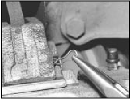
14A.2A Front brake pad locking block is secured by a clip on the inboard end
of the brake unit on certain models
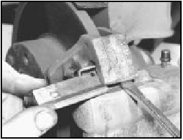
14A.2B Front brake locking block orientation with inboard retaining clip
PART B: BRAKING SYSTEM
- TURBO IE MODELS
Description
1 Disc brakes are fitted to all four wheels on
the Turbo ie models. The front disc brakes are
of different design from those used on other
models, in that the wear in the pads can be
checked without the need to remove the
caliper cylinder housing.
Front disc pads - renewal 2 Raise the front of the car and remove the roadwheels.
3 Check the thickness of the friction material on the pads through the aperture in the caliper cylinder body. If the thickness of the material is 1.5 mm or less, then the pads on both sides must be renewed (photo).
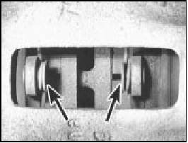
14B.3 Front disc pads (arrowed) on Turbo ie model
4 Using a ring spanner and an open-ended spanner, unscrew and remove the caliper cylinder housing lower guide bolt (photo).
Release the upper bolt, but do not remove it.
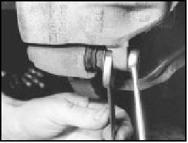
14B.4 Unscrewing the caliper cylinder housing lower guide bolt
5 Swivel the cylinder housing upwards and tie it up out of the way. There is no need to disconnect the hydraulic hose. The sensor wiring plug will have to be disconnected (where fitted).
6 Remove the pads, complete with anti-rattle springs (photo).

14B.6 Disc pad and anti-rattle spring removal
7 Clean away all dust and dirt, taking care not to inhale it as it may be injurious to health.
8 The caliper piston must now be fully depressed to accommodate the new, thicker, pads. Do this using a G-clamp or lever, but anticipate a rise in the brake fluid reservoir level by syphoning out some of the fluid using a clean syringe.
9 Fit the new pads, which must be of the same type as the originals, complete with anti-rattle springs.
10 Locate the cylinder body. The fixing bolts are of self-locking type, and should be renewed whenever they are loosened or removed. If new ones are not available, clean the threads of the old ones thoroughly and apply thread-locking fluid (photo). Tighten the bolts to the specified torque. Check that the rubber dust excluders are in good condition.
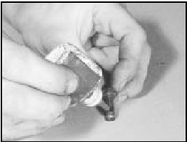
14B.10 Applying thread-locking fluid to the bolt threads
11 Reconnect the sensor wiring plug.
12 Renew the pads on the other front wheel.
13 Refit the roadwheels, and then apply the footbrake several times to position the pads against the discs.
14 Top up the brake fluid reservoir if necessary (photo).
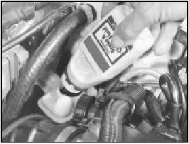
14B.14 Topping up the brake fluid reservoir (1301 cc Turbo ie model)
Front disc caliper -
removal and refitting
15 Raise the front of the car and remove the
appropriate roadwheel.
16 Using a ring spanner and an open-ended spanner, unscrew and remove the cylinder housing fixing bolts.
17 Withdraw the cylinder housing, and then, holding it firmly, release the flexible hydraulic hose union. Unscrew the cylinder body from the end of the flexible hose, and then cap the end of the hose to prevent loss of fluid.
18 If required, the disc pads can be removed and the caliper support bracket unbolted and removed.
19 Refitting is a reversal of removal, but use new fixing bolts.
20 Bleed the front hydraulic circuit.
Front disc caliper - overhaul 21 The operations are as described in Chapter 8, Section 5, paragraphs 6 to 13.
Front brake disc - inspection,
renovation or renewal
22 The operations are as described in
Chapter 8, Section 6, but the caliper fixing
bolts are secured with thread-locking fluid;
lockplates are not used.
Rear disc pads - renewal 23 Any wear in the disc pads can be observed through the aperture in the caliper cylinder body, once the car has been jacked up and the roadwheels removed (photo).
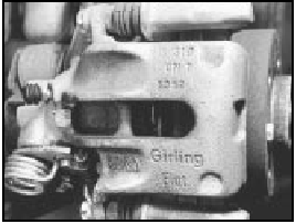
14B.23 Rear brake pad inspection aperture
24 If the thickness of the pad friction material is less than 1.5 mm, renew the pads on both sides in the following way.
25 Using a ring spanner and an open-ended spanner, unscrew the caliper cylinder body fixing bolts.
26 Withdraw the caliper and remove the disc pads, complete with anti-rattle springs (photo).
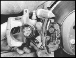
14B.26 Withdrawing the rear brake caliper
27 Clean away all dust and dirt, but avoid inhaling it, as it may be injurious to health.
28 Fully retract the caliper piston in order to accommodate the new, thicker, pads. To do this, rotate the piston clockwise, using a suitable tool engaged in the handbrake sectors (photo). Anticipate a rise in the brake fluid reservoir level by syphoning out some fluid, using a clean syringe.
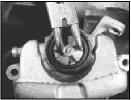
14B.28 Rotating a rear caliper piston
29 Fit the new pads, complete with anti-rattle springs (photo).
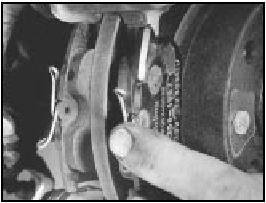
14B.29 Rear disc pad
30 Refit the caliper using new self-locking bolts, or if not available, apply thread-locking fluid to clean threads of the original bolts.
Tighten the bolts to the specified torque.
31 Apply the brake pedal several times to bring the disc pads up against the disc.
32 Top up the brake fluid reservoir if necessary.
33 Check the adjustment of the handbrake.
34 Refit the roadwheels and lower the car to the ground.
Rear disc caliper -
removal, overhaul and
refitting
35 Carry out the operations described in
paragraphs 25 to 27.
36 Disconnect the handbrake cable from the caliper. To do this, grip the cable nipple and pull it until the cable can be slipped out of its lever groove (photo). If necessary, slacken the cable adjustment.
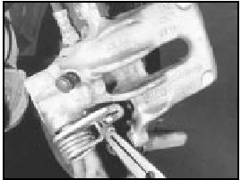
14B.36 Disconnecting the handbrake cable from the caliper lever
37 Using a pair of pliers or similar tool, turn the piston in an anti-clockwise direction until it can be removed from the cylinder.
38 Having obtained a repair kit, renew the seal and dust excluder.
39 Reassemble the piston to the cylinder, turning it clockwise as far as it will go.
40 Reconnect the handbrake cable.
41 Carry out the operations described in paragraphs 30 to 32.
Rear brake disc -
inspection, renovation
or renewal
42 The operations are as described in
Chapter 8, Section 6, but the caliper bracket
fixing bolts are of the socket-headed type and
thread-locking fluid is used, not lockplates
(photo).
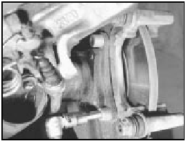
14B.42 Unscrewing a rear caliper bracket bolt
Pressure regulating valve 43 The valve renewal and adjustment operations are described in Chapter 8, Section 10, but the luggage compartment should be loaded with 45 kg and the load applied to the bracket eye should be 11 kg.
Brake pedal -
removal and refitting
44 The brake master cylinder and vacuum
servo are mounted on the left-hand side of the
engine compartment rear bulkhead. In consequence,
the brake pedal on right-hand drive
cars operates through a cross-shaft, which is
located underneath the facia panel inside the
car.
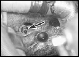
45 The cross-shaft is supported in two brackets, whose mounting nuts can be reached through cut-outs in the insulation on the engine compartment rear bulkhead (photo).
14B.45 Brake pedal cross-shaft fixed nut (arrowed) on engine compartment rear
bulkhead
46 To remove the cross-shaft, working inside the car, take off the cover from the left-hand end of the shaft, and then disconnect the servo pushrod from the crankarm on the cross-shaft (photo).
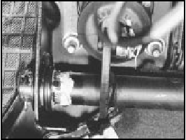
14B.46 Left-hand end of brake pedal cross-shaft
47 Disconnect the brake pedal from the right-hand crankarm on the cross-shaft (photo).

14B.47 Right-hand end of brake pedal cross-shaft
48 Disconnect the accelerator pedal by extracting the split pin which secures its pivot spindle.
49 The cross-shaft may now be removed after extracting the cotter pin from the left-hand end of the shaft.
50 Push the shaft first to the right, and then to the left, to release it from its brackets.
51 Alternatively, the cross-shaft, complete with brackets, may be removed as an assembly if the bulkhead nuts are unscrewed.
52 Removal of the brake and clutch pedals is described in Chapter 5, Section 4, but note that on hydraulic clutch models, the master cylinder will also require removal as described in Section 11 of this Chapter.
53 Refitting is a reversal of the removal procedure.
Vacuum servo unit and master
cylinder - general
54 Access to the vacuum servo unit and the
master cylinder can only be obtained after the
cooling system expansion tank has been
released and moved aside (photo).
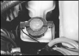
14B.54 Master cylinder/vacuum servo located next to the coolant expansion
tank (1301 cc Turbo ie model)
Antiskid system - description 55 This system is available as an option on the Turbo ie models only.
56 The purpose of the system is to prevent the wheel(s) locking during heavy brake applications. This is achieved by automatic release of the brake on a roadwheel which is about to lock up, after which the brake is re-applied. This cycle is carried out many times per second under heavy braking, retaining full steering control to avoid any hazards.
57 The main components of the system are shown in Fig. 13.102. The control module processes the signals received from the sensors, and compares them with deceleration values of the roadwheel and the slip values of the tyre, which are stored in the module memory.
58 When reference values are exceeded and wheel lock is imminent, the control module signals the pressure modulators, which in turn decrease the brake hydraulic pressure.
59 Vehicle road speeds are also taken into account by the module’s electronic circuits.
60 In order to retain optimum system performance, the tyres and wheels should always be of the type originally fitted by the vehicle manufacturer.
61 Maintenance of the system should be limited to checking the security of all electrical and hydraulic connections. Individual components are not repairable, and must be renewed complete if faulty.
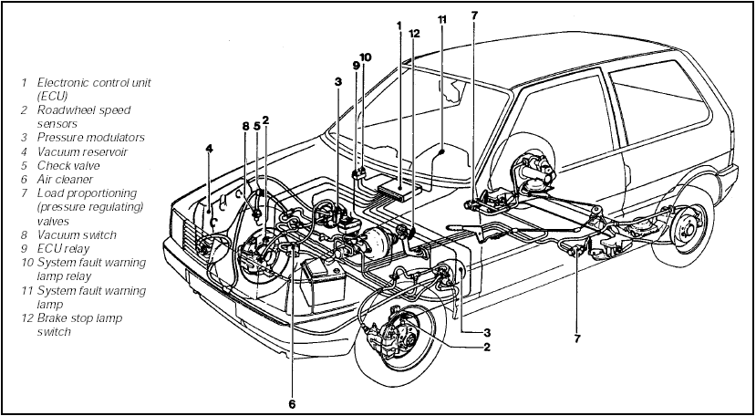
Fig. 13.102 Braking system on Turbo ie Antiskid models (Sec 14)


